


あらゆるシーンで安全と安心をサポート アイデアしだいで用途は無限に広がります
【掲載内容】
○使用例と特長
○テープスイッチ 内部構造と原理
○テープスイッチ 製品一覧
○センシングエッジ 応用と特長
○センシングエッジ 製品一覧
○バンパースイッチ
○標準形マットスイッチ(在庫即納品)
○カスタムサイズマットスイッチ(受注生産) など
◆詳細は、カタログをダウンロードしてご覧ください。
このカタログについて
| ドキュメント名 | オジデン テープ&マットスイッチ 総合カタログ |
|---|---|
| ドキュメント種別 | 製品カタログ |
| ファイルサイズ | 8.5Mb |
| 登録カテゴリ | |
| 取り扱い企業 | 大阪自動電機株式会社 (この企業の取り扱いカタログ一覧) |
この企業の関連カタログ


このカタログの内容
Page1
H01-04_cs6
1711 B 000
Page2
P1-12
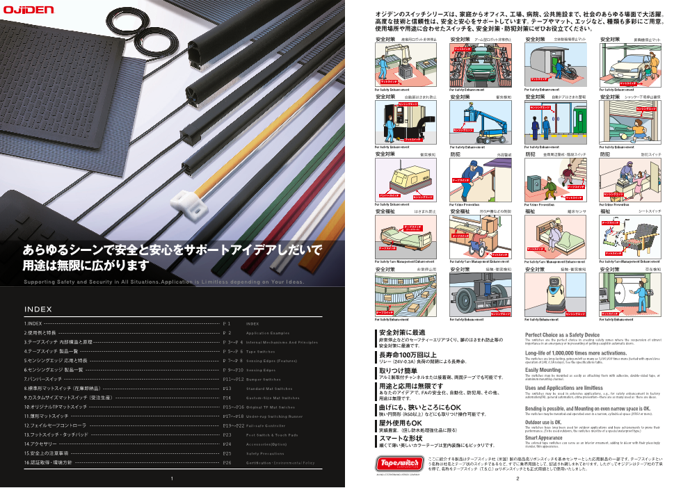
オジデンのスイッチシリーズは、家庭からオフィス、工場、病院、公共施設まで、社会のあらゆる場面で大活躍。
高度な技術と信頼性は、安全と安心をサポートしています。テープやマット、エッジなど、種類も多彩にご用意。
使用場所や用途に合わせたスイッチを、安全対策・防犯対策にぜひお役立てください。
あらゆるシーンで安全と安心をサポートアイデアしだいで
用途は無限に広がります 安全対策 非常停止用 安全対策 接触・衝突検知 安全対策 接触・衝突検知 安全対策 存在検知
Supporting Safety and Security in All Situations.Appl ication is L i mitl ess depending on Your I d eas.
INDEX
For Safety Enhancement For Safety Enhancement For Safety Enhancement For Safety Enhancement
1.INDEX P 1 INDE X
2.使用例と特長 P 2 Appl icat ion E xamples 安全対策に最適 Perfect Choice as a Safety Device
3.テープスイッチ 内部構造と原理 P 3~P 4 In te rna l Mechan isms And Pr inc ip les 非常停止などのセーフティーエリアづくり、扉のはさまれ防止等の The switches are the perfect choice in creating safety zones where the suspension of utmost
安全対策に最適です。 importance in an emergency or in preventing of getting caught in automatic doors.
4.テープスイッチ 製品一覧 P 5~P 6 Tape Swi tches 長寿命100万回以上 Long-life of 1,000,000 times more activations.
5.センシングエッジ 応用と特長 P 7~P 8 The switches are long-lasting, going on/off as many as 1,000,000 times more (tested with open/close Sens ing Edges (Features) リレー(24V-0.3A)負荷の開閉による長寿命。 operation of 24V, 0.3A relays). See the specifications table.
6.センシングエッジ 製品一覧 P 9~P10 Sens ing Edges 取りつけ簡単 Easily Mounting
アルミ製取付チャンネルまたは接着剤、両面テープでも可能です。 The switches may be mounted as easily as attaching them with adhesive, double-sided tape, or 7.バンパースイッチ P11~P12 Bumper Swi tches aluminum mounting channel.
8.標準形マットスイッチ(在庫即納品) P13 Standard Mat Swi tches 用途と応用は無限です Uses and Applications are limitless
あなたのアイデアで、FAの安全化、自動化、防犯用、その他、 The switches may be used in extensive applications, e.g., for safety enhancement in factory
9.カスタムサイズマットスイッチ(受注生産) P14 Custom-S ize Mat Swi tches 用途は無限です。 automation(FA), general automation, crime prevention--there are as many used as there are ideas.
10.オリジナルTPマットスイッチ P15~P16 Or ig ina l TP Mat Swiches 曲げにも、狭いところにもOK Bending is possible, and Mounting on even narrow space is OK.
11.薄形マットスイッチ P17~P18 狭い円筒形(R50以上)などにも取りつけ操作可能です。 The switches may be mounted and operated even in a narrow, cylindrical space (if R50 or more).Under- rug Swi tch ing Runner
12.フェイルセーフコントローラ P19~P22 Outdoor use is OK.Fa i l -sa fe Cont ro l le r 屋外使用もOK The switches have long been used for outdoor applications and have achievements to prove their
実績豊富。(但し防水処理強化品に限る) performance. (To be used outdoors, the switches must be of a special waterproof type.)
13.フットスイッチ・タッチパッド P23 Foot Swi tch & Touch Pads スマートな形状 Smart Appearance
14.アクセサリー P24 Accessor ies (Opt ion) The colored tape switches can serve as an interior ornament, adding to décor with their pleasingly 細くて薄い美しいカラーテープは室内装飾にもピッタリです。 slender, thin appearance.
15.安全上の注意事項 P25 Safet y Precaut ions
ここに紹介する製品はテープスイッチ社(米国)製の商品名リボンスイッチを基本センサーとした応用製品の一部です。テープスイッチとい
16.認証取得・環境方針 P26 Cer t ificat ion・Env iro nm e nt a l Po l i c y う名称は社名とテープ状のスイッチであるなど、すでに業界用語として、記述され親しまれております。したがってオジデンはテープ社の了承
を得て、名称をテープスイッチ(T.S.C.)orリボンスイッチとも正式用語として使用いたしました。
AN INDUCTOTHERM INDUSTRIES COMPANY
1 2
Page3
TAPE SWITCHES
テープスイッチの構造と動作原理 テープスイッチのご注文に際して
感知
部
不 eae ar
Inac
tiv
2 ve ar
ea
1 部)A
cti
知 th (L)g
5 長(感 tal le
n
o
有効 (L)T
全長
知部
3 不感 are
a
4 eInacti
v
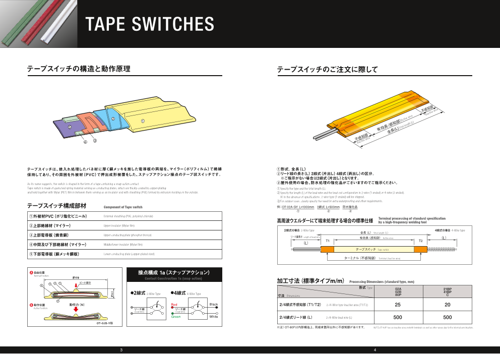
テープスイッチは、焼入れ処理したバネ材に厚く銅メッキを施した電導板の両端を、マイラー(ポリフィルム)で絶縁 ①形式. 全長(L)
保持してあり、その周囲を外被材(PVC)で押出成形被覆をした、スナップアクション接点のテープ状スイッチです。 ②リード線の長さ(L) 2線式(片出し) 4線式(両出し)の区分。
※ご指示がない場合は2線式(片出し)となります。
As its name suggests, the switch is shaped in the form of a tape containing a snap-action contact. ③屋外使用の場合、防水処理の強化品がございますのでご指示ください。
Tape switch is made of quenched spring material serving as conducting plates, which are thickly coated by copper-plating ①Specify the type and the total length (L).
and held together with Mylar (PET) film in between them serving as an insulator and with sheathing (PVC) formed by extrusion molding on the outside. ②Specify the length (L) of the lead wire and the lead-out configuration in 2-wire (1-ended) or 4-wire (2-ended).
※ In the absence of specifications, 2-wire type (1-ended) will be shipped.
③For outdoor uses, clearly specify the need for extra waterproofing and other requirements.
テープスイッチ構成部材 Component of Tape switch 例:OT-02A-GY L=1000mm 2線式 L=500mm 防水強化品
① ② ③
①外被材PVC(ポリ塩化ビニール) External sheathing (PVC, polyvinyl chloride)
高周波ウエルダーにて端末処理する場合の標準仕様 Terminal processing of standard specifi cationby a high-frequency welding tool
②上部絶縁材(マイラー) Upper insulator (Mylar film)
2線式の場合 2-Wire type 4線式の場合 4-Wire type
全長(L) Total length(L)
③上部電導板(燐青銅) Upper conducting plate (phosphor bronze) リード線長さ Length of lead wire 有効長(感知部) Active area (L)
T1 T2
④中間及び下部絶縁材(マイラー) Middle/lower insulator (Mylar film) (L)
テープスイッチ Tape switch
⑤下部電導板(銅メッキ鋼板) Lower conducting plate (copper-plated steel)
ターミナル(不感知部) Terminal (Inactive area)
A 自由位置 接点構成 1 a(スナップアクション)
Normal Position
約19 Contact Construction 1a (snap action)
2 1 ビード部分 加工寸法(標準タイプm/m) Processing Dimensions (standard type, mm)3
4
形式 Type 02A 21BP
●2線式 02B2-Wire Type ●4線式 4-Wire Type 41BP寸法 Dimensions 80P C
5
B 動作位置 動作力(N) Red Black 2/4線式不感知部(T1/T2) 2-/4-Wire type inactive area (T1/T2) 25 20
Active Position リード線 リード線
(lead wire) (lead wire)
Green White 2/4線式リード線(L) 2-/4-Wire lead wire (L) 500 500
OT-02B-Y形
※注)OT-80Pは内部構造上、両端末箇所以外に不感知部があります。 NOTE:OT-80P has an inactive area on both terminals as well as other areas due to the internal construction.
3 4
約4.5
Page4
TAPE SWITCHES
標準形テープスイッチ Standard Tape Switches
OT-02A-GY(gray) OT-02B-Y(yellow)/-B(black) OT-21BP-G(green) OT-C-BL(blue) OT-41BPM-W(white) OT-41BP-R(red)-B(black)-W(white) OT-80P(red)
形式
Type
19
形状断面
(m/m)
Cross-sectional
configuration 19 8 14 14.3 14
(mm) 22.3 14
14.3
OC-06チャンネル( ※オプション)
OC-06 mounting channel (※optional)
動作力と重さ
Operating force
and weight 約30N 重さ約110g/m 約12N 重さ約100g/m 約3N 重さ約85g/m 約3N 重さ約約62g/m 約4N 重さ約80g/m 約10N 重さ約100g/m 約2.2N 重さ約60g/m
(Approx.)
●強い作動力形(復帰力)(02A-GY) ●高感度形、低い突起部。 ●センタービートに凹凸をもたせた ●OT-41BP-Wよりも感度が敏感でセーフティー ●高感度形、高い突起部。 ●VFF0.5mm2 0.5m付
●高感度形(02B-Y、02B-B) ●応用:医療機器類の安全センサ、防犯、 高感度テープスイッチ。 エッジに内蔵しています。 ●多方向の力でも作動する。 ●10 ~15度 で 折ってスイッチ O N 、押してもスイッチ
●応用 : コンベア、エレベーター、娯楽機器のシート(マット)センサ、医療機器、各種 手元スイッチなど。 ●防水処理強化も承ります。 ●曲げ半径:約R50 ●応用:ドアエッジ、各種医療機器、駐車機器、産業機器 ON。
自動化機器や防犯用およびセーフティエッジの内蔵センサなど。 ●曲げ半径:約R50 ●曲げ半径:約R50 ●防水処理強化も承ります。 等の安全対策センサ、ベルトコンベア、工作機械の非常 ●曲げ加工はできません。
●曲げ半径:約R50 ●防水処理強化も承ります。 ●取付チャンネルOC-04形(オプション)もあり。 停止用スイッチに。 ●最大長:3メートルまで。
●防水処理強化も承ります。 ●色はR(赤)B(黒)W(白)の3色。 ●応用:ベッドやイスの内部に、衝突感知。
●取付チャンネルOC-06形(オプション)もあり。 ●最大長:200メートルまで。 ●両端末箇所以外に不感知部があります。
応用と特長 ●曲げ半径:約R50
Applications and ●防水処理強化も承ります。
features ●取付チャンネルOC-04形(オプション)もあり。
● High sensitivity, High protrusion.
● Multi-directional activation (See the arrows in the diagram abore.)
● High operating force (recovery) (02A-GY) ● Application: door edges, various medical equipment,parking equipment,
● High sensitivity (02B-Y, 02B-B) safety sensor of industrial equipment, conveyor, EMG switch for machine tool. ● with VFF 0.5 mm2, 0.5 m (standard)
● Applications: conveyers, elevators, seat (mat) sensor for entertainment equipment, medical equipment, various ● High sensitivity, Low protrusion. ● Extra high sensitivity (higher than that of OT-41BP-W and ● M aximum length: 200 m. ● 2-way activation (in response to bending at 10 to 15 or pressing)
automation equipment, built-in sensors for crime-prevention devices and safety edges. ● Applications: safety sensors in medical equipment, ● High sensitivity (convexo-convex surface) primarily built in safety edges) ● 3colors:Red,Black,White ● No bending processing.
● Bending R50 (approx.) crime-prevention and on-hand switches. ● Extra waterproof process is available on ● Bending R50 (approx.) ● Bending R50 (approx.) ● Maximum length: 3 m.
● Extra waterproof process is available on upon request. ● Bending R50 (approx.) upon request. ● Extra waterproof process is available on upon request. ● Extra waterproof process is available on upon request. ● Applications: inside beds/chairs; collision prevention.
● OC-06 mounting channel (optional). ● Extra waterproof process is available on upon request. ● Bending R50(approx) ● Mounting channel: OC-04 (optional) ● Mounting channel: OC-04 (optional) ● Inactive area in addition to on both terminals.
取付アルミチャンネル(オプション)Aluminum Mounting Channel (optional)
OC-04適用形式(OT-41BP,TS3) OC-06適用形式(OT-02A,02B) 定格 Ratings
◆最大長2M(※穴あけ加工はオプション) 定格電圧・電流 Rated voltage/current AC/DC28V-1A(最少電圧、電流値・5V20mA以上)
◆寸法、取り付け方法など、詳細はP23へ
◆チャンネルの長さは分割となる場合があります。 耐電圧 Withstand voltage AC 500V(1分間) AC 500V (1min )
OC-04: for OT-41BP, TS3 OC-06: for OT-02A, 02B 外周警戒用センサ
♦The length of channel is 2m max. (Holes may optionally be dril led.) 接点寿命 Contact life 100万回(リレー24V-0.3A負荷)以上 1,000,000 times activations or more. (tested with relay; 24V, 0.3 A load)
♦For details (e.g., dimensions, mounting method), see P12.
♦Channel may be shipped in par ts depending on its length. 動作力 Operating force 約3N~30N(ø15押圧板) 3N~30N approx. (underφ15 pressing plate)
絶縁抵抗 Insulation resistance 100MΩ以上(DC500Vメガーにて) 100 MΩ or more (by 500 VDC insulation tester)
屈曲性(テープスイッチ)Bending Characteristics (tape switch) 接触抵抗 Contact resistance 1.0Ω以下(動作力以上のとき) 1.0 Ω or less (if under operating force or more)
◎上下垂直方向(曲げ半径約R50可能) ○ はさまれ防止用センサ 使用温度範囲 Operating Temp Range -10℃~+60℃
◎Perpendicular direction (up/down).
Permit t ing bending R50 approx. 耐荷重 Withstand load 1470N(ø100押圧板1分間) 1470N (underφ100 pressing plate for 1 min)
×水平方向 保護構造 IP class 防滴形(ⅠP 54相当) Drip-proof (IP-54 equivalent)
×Lateral direct ion ×
リード線 VFF 0.75 mm
2, 0.5m(標準)※リード長 変更可 w/ VFF 0.75 mm2, 0.5m ※Change of lead wire-length is optionally available
Lead wire
○ ※OT-80P:VFF 0.5mm2, 0.5m ※OT-80P:VFF 0.5mm
2, 0.5m
非常停止用センサ
5 6
4.5
6 1.5
7.5
4
3
4
5
6.5
4
Page5
SENSING EDGES
応用と特長 Applications and Features チャンネルの名称 CHANNEL DESIGNATIONS
自動ドア(エレベーター、車両、住宅ドア、高速シャッタードア)や各種機械類の挟まれ防止、医療機器等の非常停止、 ◆Fチャンネルとはアルミフラットタイプを示す。 Fチャンネル Channel F
その他無人車両(バンパー)などの衝突検知センサとして有効です。 ◆Aチャンネルとはアルミアングルタイプを示す。
The sensing edge serves as an effective means of prevention of getting caught in automatic doors and machines, and also be used for emergency stop of medical ◆チャンネルのみご注文の場合、各形式名とF&Aチャンネルの区分を明記ください。
equipment, collision detection of AGV,etc.
♦Channel F indicates the aluminum flat type.
Aチャンネル Channel A
♦Channel A indicates the aluminum angle type.
定 格 Ratings ♦W hen placing an order for channel only, please indicate the each sensor type and the channel designation (F or A).
定格電圧・電流 Rated voltage/current AC/DC28V-1A(最少電圧、電流値・5V20mA以上)
耐電圧 Withstand voltage AC 500V(1分間) AC 500V (1min )
※形式により寸法は異なります
接点寿命 Contact life 100万回(リレー24V-0.3A負荷)以上 1,000,000 times activations or more. (tested with relay; 24V, 0.3 A load) (詳細P9,P10)
テープ状スイッチの代表的構造 ※Dimensions differ deperding on type 動作力 Operating force 約9N~30N(ø15押圧板) 9N~30N approx. (underφ15 pressing plate) TYPICAL CONSTRUCTION OF A TAPE SWITCH (For details,see P9-10)
絶縁抵抗 Insulation resistance 100MΩ以上(DC500Vメガーにて) 100 MΩ or more (by 500 VDC insulation tester) ①全形式ともFチャンネル付、標準品です。
接触抵抗 Contact resistance 1.0Ω以下(動作力以上のとき) 1.0 Ω or less (if under operating force or more) ②長いチャンネルは継いで使用します。
③チャンネルは別途、穴あけ加工してから取付けします。(ネジ径はM3~M6
使用温度範囲 Operating Temp Range -10℃~+60℃
程度で固定する/形式により選択)
耐荷重 Withstand load 1470N(ø100押圧板1分間) φ OT-08D-Bに曲げ加工を施したもの1470N(under 100 pressing plate for 1 min) ④外部ハウジングはチャンネルに合せ片側よりカバー溝にはめこむ。もう片側 垂直曲げ(MIN-R100)
保護構造 IP class 防滴形(ⅠP 54相当) Drip-proof (IP-54 equivalent) の溝部に家庭用洗剤液等を塗り、押し込みながら、両溝に、しっかりとはめ
リード線 Lead wire VFF 0.75 mm2, 0.5m(標準)※リード長 変更可
込んでセットします。(説明書商品添付)
w/ VFF 0.75 mm2, 0.5m ※Change of lead wire-length is optionally available
⑤内蔵テープスイッチの交換も簡単に差し替えできます。
⑥垂直曲げ加工R100程度(以上)が可能です。(OT-08D-Bのみ、写真参照)
リード線 2線式と4線式 ①All sensor type come standard with a channel F. 2-Wire Type and 4-Wire Type ②A long channel may be formed by joining channel segments.
③Drill holes in the channel (separately) before starting the mounting work.(Use screws of M3 to M6 (dia.) for fixing depending on model.
◆4線式制御回路(断線検知器)の併用を標準仕様としてお勧めします。 前方 ④While keeping the external housing against the channel, fit it into the groove of cover along one side first, then use a solution of a household detergent to the
この場合、4線式リード線が必要となります。(P.17~20参照) groove-cover of the other side, and press the housing firmly in place in both grooves. (See the attached User Guide with product)⑤The internal built-in tape switch may easily be replaced.
◆リード線の長さ(L)と引き出し方向、「片出し」または「両出し」の区分など、1台より、お受けします。 ⑥OT-08D-B allows bending process up to R100 as minimum. Refer to Photo.
♦4-wire control circuit (open circuit detector) for use in combination is recommended as part of standard specifications. 後方
※ The circuit requires 4-wire lead.(Refer to P17~20) ●使用例(非常停止・検知用)
♦When placing an order, please specify length and pull-out-direction (1-End or 2-End ) of lead wire. センシングエッジ
センシングエッジ
例:OT-10BP-B L=1000mm 4線式片出し L=500mm
2線式 2-Wire Type 4線式(両リード) 4-Wire Type
センシングエッジ
フットスイッチ
SENSING EDGES SENSING EDGES
自動扉の挟まれ防止用センサ 自動扉の挟まれ防止用センサ 衝突検知用センサ
4線式(両リード片出し) 4-Wire Type(Both leads from 1-End)
SENSING EDGES
タイヤガードの衝突検知用センサ サービスロボットの衝突検知用センサ AGVの衝突検知用センサ
7 8
Page6
SENSING EDGES
センシングエッジ SENSING EDGES
OT-10BP-B(black)R(red) OT-08D-B(black) OT-TS6F-R(red) B(black) OT-TS16F OT-TS26F OT-TS3F-(Y yellow) B(black) R( red)OT-C-BL(blue) OT-TS47F OT-TS57F
形式
Type
クランプ
●E⦆0.1~10 ●E⦆0.1~7 ●E⦆0.1~2.4 ●E⦆0.1~2.4 ●E⦆0.1~2.4 ●E⦆0.1~2.4 ●E⦆0.1~2 ●E 0.1~3
●F⦆0.1~2 ●F⦆0.1~2 ●F&A 0.1~2.4 ●F&A 0.1~2.4 ●F&A 0.1~2.4 ●F&A 0.1~2.4 ●F&A 0.1~2 ●F 0.1~2
全長(L)
外部ハウジング 2 テープ実長
External housing
外部ハウジング 18 一体成形センサ 取付ピッチ
テープスイッチ External housing Integrated type sensor
形状断面 Tape switch 18 12
(m/m)
Cross-sectional
configuration
(mm) 22 30 18 17.5
Fチャンネル Channel F 25.4
29
Fチャンネル Fチャンネル
8
Channel F Channel F Fチャンネル Fチャンネル
24
Channel F Channel F
29
動作力と重さ
Operating force 約17N 重さ約490g/m 約19N 重さ約690g/m 約9N 重さ約330g/m 約14N 重さ約390g/m 約30N 重さ約760g/m 約13N 重さ約950g/m 約13N 重さ約1500g/m 約27N 重さ約280g/m
and weight
(Approx.)
縮みしろ
(m/m) 約 3 約 6 約 1~2 約 6 約9 約25 約60 約 1
Over travel(m/m)
●外被材 : PVC(ポリ塩化ビニール)。 ●外被材:EPDM(エチレンプロピレンゴム) ●外被材 : PVC(ポリ塩化ビニール) ●アングルチャンネルのご注文の際は、 ●外被材 : PVC(ポリ塩化ビニール) ●外被材 : TPE(ポリオレフィン系エラストマー) ●アングルチャンネルのご注文の際は、形式末尾のFを削除し、 ●外被材 : PVC(ポリ塩化ビニール)
●小型エッジ:即作動型。 ●中型エッジ:高感度型。 ●ミニエッジ:即作動型、高感度外郭スイッチ。 形式末尾のFを削除しAと表示して ●中型エッジ:即作動型、側面作動に Aと表示してください。●大型エッジ:即作動型。 例:OT-TS47A、OT-TS57A ●外被カバーとも一体成形型。 ください。
●2色:B(黒)、R(赤)。 ●応用:衝突検知用、機械類、医療機器類、 ●2色:B(黒)、R(赤()TS6形のみ) 例:OT-TS6A-RorB、OT-TS16A 優れ、動作後の動きを軽減する。 ●急速な作動と低速の作動にも対応可能。 ●アングルチャンネルは、納期を要する場合があります。 ●マイクロエッジ:即作動型。
●応用:衝突検知用、機械類、医療機器類、 ドア、バンパーなど。 ●応用:動きドア、医療テーブル、機械類端など。 ●アングルチャンネルは、納期を要する ●応用:機械エッジゲート、舞台リフト、 ●急・高・低速のショックも軽減、作動を優先するエッジ。 ●3色:R(赤)、B(黒)、Y(黄)
ドア、バンパーなど。 ●エンドキャップ:CR(両サイド付) ●固定ネジ径:皿ネジM3~M4推奨。 場合があります。
Aチャンネル ChannelA
バンパー、エレベータードアなど。 ●応用:高速のドアスイッチ、体育館ドア、アコー ●応用:自動ドア、医療機器、フットスイッチ。
●エンドキャップ:CR(両サイド付) ●固定ネジ径:皿ネジM4~M6推奨。 ●エンドキャップ:PVC(オプション) Aチャンネル ChannelA ●固定ネジ径:皿ネジM4~M6推奨。 ディオンドア、搬送車等のバンパースイッチなど。 ●固定ネジ径:チャンネル皿ネジM3推奨。
●固定ネジ径:皿ネジM3~M4推奨。 ●Fチャンネルのみ。 ●F&A両チャンネルともあり。 ●エンドキャップ:PVC(オプション) ●固定ネジ径:皿ネジM4~M6推奨。 ●エンドキャップはクランプ(POM)にて兼用。
●Fチャンネルのみ。 ●垂直曲げ加工 約R100可 ●F&A両チャンネルともあり。 ●エンドキャップ:CR(オプション) ●Fチャンネルとクランプ付(。標準品)
(垂直曲げ加工R100程度可能です) ●アングルチャンネルのご注文の際は、 ●F&A両チャンネルともあり(。オプション:TS47・57形兼用) (※形状寸法:P16参照)
形式末尾のFを削除し、Aと表示してください。
例:OT-TS26A
応用と特長 ●アングルチャンネルは、納期を要する 場合があります。 Aチャンネル ChannelA
Applications and
features
●External sheathing: PVC (polyvinyl chloride)
●Medium-size edge: instantaneous activation type
which is excels in lateral operation to reduce
movement of over travel.
●Applications: machine edge gates, stage lifts, ●External sheathing: TPE (Thermoplastic Polyolefin Elastomer)
● External sheathing: EPDM bumpers, elevator doors, etc. ● Large-size edge: instantaneous activation type.
(ethylene propylene diene monomer) ●External sheathing: PVC (polyvinyl chloride) ●Fixing screw diameter: M4 to M6 flat head screw ●Reacting to instantaneous and low-speed operation. ● External sheathing: PVC (polyvinyl chloride)
●Medium-size edge: high sensitivity type. ●Mini edge:instantaneous activation type, recommended. ● Reduction of shock from instantaneous and ● Integrated formation with external cover.
●External sheathing: PVC (polyvinyl chloride) ●Micro edge: instantaneous activation type.
● ●Applications: collision detection; machinery,
high sensitive outer-switch. ●End cap: PVC optional. low/high-speed operation (operation is priority)
Small-size edge: instantaneous activation type. medical equipment, doors, bumpers, etc. ●2Color; black (B), red (R); TS6 only. ●Channels F or A: Both available. ● Applications: high-speed door switches, gym ●3colors:Red, Black,Yellow.●2Colors:Black,Red. ●Applications: moving doors, medical tables, doors, accordion doors, vehicle bumper switches, etc. ● Applications: automatic doors, medical
●Applications: collision detection; machinery, medical ●End cap: standard (both ends). machinery, etc. ● When placing an order for an angle channel, ●When placing an order for an angle channel, delete ● Fixing screw diameter: M4~M6 flat head equipment, foot switches. equipment, doors, bumpers, etc. ●Fixing screw diameter: M4~M6 flat head screw the suffix F of the model designation, and specify A ● Fixing screw diameter: M3 flat head screw
●End cap: standard (both ends) recommended. ●Fixing screw diameter: M3~M4 flat head screw
delete the suffix Fof the model designation, screw recommended. ●When placing an order for an angle channel, delete the suffix
in its place. recommended (channel)
●Fixing screw diameter: M3~M4 flat head screw ●Channel F only. recommended.
and specify A in its place.
、 ● End cap: CR optional. F of the model designation, and specify A in its place.EX:OT-TS6A-RorB OT-TS16A EX:OT-TS26A ● End cap: none, but with clamp instead.
recommended. ●Bending in perpendicular direction: ●End cap: PVC optional. ● Angle channel may need a lead time more ●Angle channel may need a lead time more than ● Channels F or A: Both available. EX:OT-TS47A、OT-TS57A ● Chanel F, clamp: standard.
●Channel F only. R100 approx. ●Channels F or A :Both available. than Flat channel. Flat channel. (option: for both TS47/57) ●Angle channel may need a lead time more than Flat channel. (※For configuration and dimensions, see P16.)
●E(エッジ):外部ハウジング(保護カバー)と製作可能長さ(L/m)を示す。 ●E(edge) indicates the external housing (protective cover) and available production lengths (L, m).
◆記号説明 ♦Symbols Used
●F(フラット)●A(アングル):アルミチャンネル名と長さを示す。(長いものは継いで使用する) ●F (flat) ●A (angle): indicates the aluminum channel configuration and length. (A long channel may be formed by joining channel segments.)
9 10
7.5
19
8
25
8
4.5
7.5
15.5
23
8
8 44..55 14
22
32 11 27
38
11
13 40
53
32.5
13
13 73
86
7
12
44
P=33
4.2
Page7
Bumper Switches
応用と特長 Applications and Features バンパースイッチのご注文に際して How to Order
無人搬送車、医療・介護関連ロボット、大型X・Yテーブル、
各種可動装置に設置し、未然に事故を防ぎます。 2-R
●ご用命の際は、下記をご指定ください。
• When placing an order, provide the following information.
Bumper Switches may be installed in unmanned vehicles, medical/care-related robots, ◆ L 長さ length(mm) ◆ R コーナー半径 corner radius(R≦D-30)
large-scale X/Y tables, or other moving equipment for prevention of accidents in advance. ◆ D 奥行 depth(mm) ◆ B・E 取付ねじ位置 mounting screw position
◆ H 高さ height(mm) ◆ C リード線引出位置 lead wire lead-out position
※H.Dの最小寸法は50mm目安です。 ※コーナー半径は30Rより。
B E B ※The minimum H and D dimensions are 50 mm (reference only). ※Corner radius is from 30R.
最小25 最小25
min. min.
C
A
A-A断面(S型) A-A断面(D-1型) A-A断面(D-2型)
A A-A Cross Section (S type) A-A Cross Section (D-1 type) A-A Cross Section (D-2 type)
L +- 2.5
※h寸法をご指定下さい。 ※Indicate dimension (h)
その他形状例(オプション)
Other Shape (Option)
仕 様 Specifications
標準 オプション
Standard Optional
定 格 電 圧・電 流
Rated voltage/current AC/DC28V-1A ※別途詳細はお問い合わせください (Contact us about details)
外 被 ビニルレザー ビニルレザー その他(別途ご相談下さい。)
External sheathing Vinyl leather Vinyl leather Other(Contact us)
外 被 色 黒 ご指定色 黒 グレー 金属光沢
External sheathing color Black User-specified Black Gray Metallic gloss
外 被 縫 製 ステッチ縫製 L 長さ mm
External sheathing sewing Stitching
緩 衝 材 ウレタンフォーム D 奥行 mm
Cushioning material Urethane foam
ベ ー ス 板 合板15mm厚 最大長2,400mm 鉄板、アルミニウム、硬質塩化ビニル
Base plate Plywood (15 mm thick; 2400 mm max. in length) Steel sheet, aluminum, hard vinyl chloride
H 高さ mm
取 付 ね じ M8 L=30mm ご指定
Mounting screw As specified by user R コーナー半径 R≦D-30
動 作 力 約30N
Operating force Approx.30N B 取付ねじ位置
線 式 4線式
Wire type 4-wire or 2-wire type (Standard setting is 4-wire) C リード線引出位置
リ ー ド 線 VFF 0.3mm2 赤黒×2 ご指定
Lead wire VFF 0.3mm2 red, black x 2 As specified by user ○ 特注取付ねじの場合 -M 1=
リード 線 の 長さ 500mm ご指定
Lead wire length As specified by user ※H.D の最小寸法は 50mm 目安です。
※バンパースイッチはカスタム品ですので、図面にてご指示ください。
HPより専用記入用紙がダウンロードできます。
※ The bumper switches are completely custom-made items. Please instruct specifications by such as providing a drawing,etc,.
11 12H +- 2 ● D +- 3
標準長:30
Standard length
h
h2 h1
Page8
P13-14
MAT SWITCHES CUSTOM MAT SWITCHES
応用と特長 Applications and Features. カスタム(別注)サイズのご注文について Placing Orders for Custom-size Mat Switches
産業用ロボット、NC工作機械の周辺や立入禁止地帯造り、自動ドア、防犯用など、危険を未然に防ぐために幅広く活用できます。 右記①~③をご指示ください。
1. 長寿命、高信頼性のテープスイッチ内蔵 ◆。 1枚あたりの最大サイズ ※設置エリア等に合わせてマットスイッチを連結することも可能です。
2. 万一破損、断線の場合は修理可能。 タテ1200×ヨコ3000×厚み10・14T
3. 耐油性(NBR)、非耐油性(NR)ともスリップ防止用(ブロック形、筋形)高品質ゴムを採用。 ※オレンジ色のみタテ1000×ヨコ2000×厚み15T H W T
◆カスタムマットスイッチをご使用の際にはフェイル 厚さ10
The Mat switches have been utilized widely for eliminating and preventing hazards in advance such as creating 区 分 タテ ヨコ と14ミリ リード線 セーフコントローラとの併用をおすすめいたします。 × × Thickness
off-limits zone around a industrial robots or NC tooling machine by installing it. Also used for an automatic doors, Category Height Width Lead wire◆短納期にて製作いたします。 (10 or 14 mm)
crime prevention and etc.,. ◆標準設定 リード出し位置:右上角 リード長さ:1.5m
1.Long-life, High-reliability tape switch is built in. ① ② ③
2.Excels in resisting impact as from a dropping object. Permits repairs in the event of damage or line disconnection.
3.Both oil-resistive type (NBR) and non oil-resistive type (NR) are made of high guality rubber which is designed for ♦Maximum Size Per Mat 材質と色 サイズ
slip-prevention(block/rip texture) 1200 H x 3000 W x 10 or 14 T NBR(耐油性) 寸法(m/m) 引出口存在検知用センサ ※If orange, 1000 H x 2000 W x 15 T. NR(非耐油性)
♦ 形状(略図)
リード線の位置
定 格 When using a mat switch, a combination with a および長さRatings fail-safe controller is recommended. Material and color Size
♦In spite of custom order, it will be manufactured NBR Dimensions(m/m ) Lead-out
定格電圧・電流 (Oil-resistR aated voltage/current AC/DC28V-1A AC/DC28V-1A w ithin a short lead time. nce )NR Configuration
position and length
♦ St oa fn d lea ard d s wet irti eng : A 1.5M-length of lead wire (Non oil-resistance) (schematic drawing)
耐電圧 Withstand voltage AC 500V(1分間) AC 500V (1min) will be pulled out from the top right of corner.
接点寿命 Contact life 100万回(リレー24V-0.3A負荷)以上 1,000,000 times activations or more. (tested with relay; 24V, 0.3 A load) 仕 様 標 準 オプション
Specifications Standard Optional
動作力 Operating force 約50N~60N(ø90押圧板) 50N~60N approx. (underφ90pressing plate) 耐油
(NBR) ※厚み15Tのみ
絶縁抵抗 Insulation resistance 100MΩ以上(DC500Vメガーにて) 100 MΩ or more (by 500 VDC insulation tester) 上ゴ Oム il-resistance
※15 T (thickness) only.
黒(筋ゴム) 黒(フラット) オレンジ(花柄)
(NBR)
Upper Black (rib-texture rubber)~ Black (flat) Orange (flower pattern)接触抵抗 Contact resistance 0.05~1.6Ω以下(動作力以上のとき) 0.05 1.6Ωor less (if under operating force or more)
rubber 非耐油
耐荷重 Withstand load 1960N(ø100押圧板1分間) 1960N(underφ100 pressing plate for 1 min) (NR)Non oil-resistance グレー(筋ゴム) 緑(筋ゴム) 黄(筋ゴム) 赤(筋ゴム) 黒(筋ゴム) 黒(フラット
( )NR)
保護構造 IP class 防滴形(IP 54相当) Drip-proof (IP54 equivalent) Gray (rib-texture rubber) Green (rib-texture rubber) Yellow (rib-texture rubber) Red (rib-texture rubber) Black (rib-texture rubber) Black (flat)
リード線 Lead wire S-VCTF0.75mm2 ×4芯1.5M付き W/S-VCTF0.75mm2×4strands-1.5m 寸法(形状)とリード線の引き出し位置と色分け〔R:(赤)、G:(緑)、W:(白)、B:(黒)〕
●端末マット(4線式片リード形) ●連結マット(4線式両リード形)
安全エリアづくりに4線式マットスイッチ ●Terminal Mat (4-wire 1-ended lead-out) W ●Joint Mat (4-wire 2-ended lead-out)4-Wire Mat Switch for Creation of a Safety Zone D
コ 上部電導板 上部電導板
●OM-754形ブロック形ゴム(黒)耐油性(NBR)●OM-7541形筋形ゴム(灰)非耐油性(NR)●OM-1074形筋形ゴム(黒)耐油性(NBR) ン R A H R R
ト E
ロ G G G下部電導板 B 下部電導板
●OM-754/Block-texture rubber (black), oil-resistive type (NBR) ●OM-7541/Rib-texture rubber (gray), non oil-resistive type (NR) ーW W Wラ
●OM-1074/Rib-texture B rubber (black), oil-resistive type (NBR) B B
C F
※端末マットのリード線出口は、A 右上が標準仕様です。
※In the absence of specifications for lead-out position,standard setting A is shipped.
カスタム・マルチゾーンマットスイッチ Custom/Multi-zone Mat Switch
◆カラー組合せ、変形、くりぬき、連結などが可能です。
◆A combination with different colors, altered or hollowed-out shape, and jointed of Mat switches are available (Option)
●病院・介護施設など ●AGV.ロボット用、工場など ●特殊スペース、工場・病院など
●Hospitals, nursing care facilities ●Factories for AGVs, robots, etc.,. ●Special spaces (factories, hospitals)
700 1000 ベット
Bed AGVゾーン
ロボット
AGV zone Robot
マットスイッチ 形 式一 覧 表 Table of Mat Switch Models
形 式 サイズ(m/m) 使用温度範囲H×W× リード線 表T 面模様(色) 材 質 動作力 (℃) 保護構造(IP) 重さ(kg)約 在庫区分
Type Size(m/m) Lead wire Surface pattern(color) Material Operating Operating temp force range Ip class
Weight
(approx.) Inventory
基本構造と名称 Basic Construction and Parts
H×W×T
ブロックパタ 耐ー 油ン 性ゴム 筋形ゴム スイッチ素子 リード線:S-VCTF 0.75mm2
OM-754 500×700×13 (黒) (NBR) 5.0 ○ Rib-texture Switch-
渡り線 4芯1.5M付(標準) 断面部分拡大図 Enlargement of Cross Section
Oil-resistive rubber
S-VCTF Block (black) rubber element
Crossover
(NBR) (外径約φ7.5 黒色) ●筋形ゴム断面 Cross Section of Rib-texture Rubber
0.75mm²×4芯 上ゴム
非耐油性ゴム 防滴形 Lead wire: standa1 rd
25 ピッチ55 Upper rubber 25
.5M付き 筋ゴム (IP 54相当) with S-VCTF 55(pitch)
OM-7541 (N5 R00 )×700×10 (灰) 約50N -10~+60℃ 4.0 ○ (0.75 mm2, 4-strand, 1.5 m)
W/S-VCTF Rib (gray)
Non oil-resistive rubber (approx.)
(NR) Drip-proof H スイッチ固定バンド
0.75mm²×4 (IP-54 equivalent) Switch-fixing band
strands-1.5m 耐油性ゴム筋ゴム ( 25 15
下ゴム
OM-1 N0 B7 R4 )700×1000×14 (黒) 8.5 ○ Lower rubberOil-resistive rubber
Rib (black) 接合面全周(不感知部) スイッチ固定 スイッチ素子(NBR) 接合面・枠ゴム
W Joint surface of whole circumference バンド (テープスイッチ) Joint surface/
◆在庫区分:○印在庫品を示す。 ( Inactive area) Switch-fixing
Switch-element
( fT raa mpe e rubband swit
b
c eh r)
13 14
500
700
14
Page9
MAT SWITCHES CUSTOM MAT SWITCHES
応用と特長 Applications and Features. カスタム(別注)サイズのご注文について Placing Orders for Custom-size Mat Switches
産業用ロボット、NC工作機械の周辺や立入禁止地帯造り、自動ドア、防犯用など、危険を未然に防ぐために幅広く活用できます。 右記①~③をご指示ください。
1. 長寿命、高信頼性のテープスイッチ内蔵 ◆。 1枚あたりの最大サイズ ※設置エリア等に合わせてマットスイッチを連結することも可能です。
2. 万一破損、断線の場合は修理可能。 タテ1200×ヨコ3000×厚み10・14T
3. 耐油性(NBR)、非耐油性(NR)ともスリップ防止用(ブロック形、筋形)高品質ゴムを採用。 ※オレンジ色のみタテ1000×ヨコ2000×厚み15T H W T
◆カスタムマットスイッチをご使用の際にはフェイル 厚さ10
The Mat switches have been utilized widely for eliminating and preventing hazards in advance such as creating 区 分 タテ ヨコ と14ミリ リード線 セーフコントローラとの併用をおすすめいたします。 × × Thickness
off-limits zone around a industrial robots or NC tooling machine by installing it. Also used for an automatic doors, Category Height Width Lead wire◆短納期にて製作いたします。 (10 or 14 mm)
crime prevention and etc.,. ◆標準設定 リード出し位置:右上角 リード長さ:1.5m
1.Long-life, High-reliability tape switch is built in. ① ② ③
2.Excels in resisting impact as from a dropping object. Permits repairs in the event of damage or line disconnection.
3.Both oil-resistive type (NBR) and non oil-resistive type (NR) are made of high guality rubber which is designed for ♦Maximum Size Per Mat 材質と色 サイズ
slip-prevention(block/rip texture) 1200 H x 3000 W x 10 or 14 T NBR(耐油性) 寸法(m/m) 引出口存在検知用センサ ※If orange, 1000 H x 2000 W x 15 T. NR(非耐油性)
♦ 形状(略図)
リード線の位置
定 格 When using a mat switch, a combination with a および長さRatings fail-safe controller is recommended. Material and color Size
♦In spite of custom order, it will be manufactured NBR Dimensions(m/m ) Lead-out
定格電圧・電流 (Oil-resistR aated voltage/current AC/DC28V-1A AC/DC28V-1A w ithin a short lead time. nce )NR Configuration
position and length
♦ St oa fn d lea ard d s wet irti eng : A 1.5M-length of lead wire (Non oil-resistance) (schematic drawing)
耐電圧 Withstand voltage AC 500V(1分間) AC 500V (1min) will be pulled out from the top right of corner.
接点寿命 Contact life 100万回(リレー24V-0.3A負荷)以上 1,000,000 times activations or more. (tested with relay; 24V, 0.3 A load) 仕 様 標 準 オプション
Specifications Standard Optional
動作力 Operating force 約50N~60N(ø90押圧板) 50N~60N approx. (underφ90pressing plate) 耐油
(NBR) ※厚み15Tのみ
絶縁抵抗 Insulation resistance 100MΩ以上(DC500Vメガーにて) 100 MΩ or more (by 500 VDC insulation tester) 上ゴ Oム il-resistance
※15 T (thickness) only.
黒(筋ゴム) 黒(フラット) オレンジ(花柄)
(NBR)
Upper Black (rib-texture rubber)~ Black (flat) Orange (flower pattern)接触抵抗 Contact resistance 0.05~1.6Ω以下(動作力以上のとき) 0.05 1.6Ωor less (if under operating force or more)
rubber 非耐油
耐荷重 Withstand load 1960N(ø100押圧板1分間) 1960N(underφ100 pressing plate for 1 min) (NR)Non oil-resistance グレー(筋ゴム) 緑(筋ゴム) 黄(筋ゴム) 赤(筋ゴム) 黒(筋ゴム) 黒(フラット
( )NR)
保護構造 IP class 防滴形(IP 54相当) Drip-proof (IP54 equivalent) Gray (rib-texture rubber) Green (rib-texture rubber) Yellow (rib-texture rubber) Red (rib-texture rubber) Black (rib-texture rubber) Black (flat)
リード線 Lead wire S-VCTF0.75mm2 ×4芯1.5M付き W/S-VCTF0.75mm2×4strands-1.5m 寸法(形状)とリード線の引き出し位置と色分け〔R:(赤)、G:(緑)、W:(白)、B:(黒)〕
●端末マット(4線式片リード形) ●連結マット(4線式両リード形)
安全エリアづくりに4線式マットスイッチ ●Terminal Mat (4-wire 1-ended lead-out) W ●Joint Mat (4-wire 2-ended lead-out)4-Wire Mat Switch for Creation of a Safety Zone D
コ 上部電導板 上部電導板
●OM-754形ブロック形ゴム(黒)耐油性(NBR)●OM-7541形筋形ゴム(灰)非耐油性(NR)●OM-1074形筋形ゴム(黒)耐油性(NBR) ン R A H R R
ト E
ロ G G G下部電導板 B 下部電導板
●OM-754/Block-texture rubber (black), oil-resistive type (NBR) ●OM-7541/Rib-texture rubber (gray), non oil-resistive type (NR) ーW W Wラ
●OM-1074/Rib-texture B rubber (black), oil-resistive type (NBR) B B
C F
※端末マットのリード線出口は、A 右上が標準仕様です。
※In the absence of specifications for lead-out position,standard setting A is shipped.
カスタム・マルチゾーンマットスイッチ Custom/Multi-zone Mat Switch
◆カラー組合せ、変形、くりぬき、連結などが可能です。
◆A combination with different colors, altered or hollowed-out shape, and jointed of Mat switches are available (Option)
●病院・介護施設など ●AGV.ロボット用、工場など ●特殊スペース、工場・病院など
●Hospitals, nursing care facilities ●Factories for AGVs, robots, etc.,. ●Special spaces (factories, hospitals)
700 1000 ベット
Bed AGVゾーン
ロボット
AGV zone Robot
マットスイッチ 形 式一 覧 表 Table of Mat Switch Models
形 式 サイズ(m/m) 使用温度範囲H×W× リード線 表T 面模様(色) 材 質 動作力 (℃) 保護構造(IP) 重さ(kg)約 在庫区分
Type Size(m/m) Lead wire Surface pattern(color) Material Operating Operating temp force range Ip class
Weight
(approx.) Inventory
基本構造と名称 Basic Construction and Parts
H×W×T
ブロックパタ 耐ー 油ン 性ゴム 筋形ゴム スイッチ素子 リード線:S-VCTF 0.75mm2
OM-754 500×700×13 (黒) (NBR) 5.0 ○ Rib-texture Switch-
渡り線 4芯1.5M付(標準) 断面部分拡大図 Enlargement of Cross Section
Oil-resistive rubber
S-VCTF Block (black) rubber element
Crossover
(NBR) (外径約φ7.5 黒色) ●筋形ゴム断面 Cross Section of Rib-texture Rubber
0.75mm²×4芯 上ゴム
非耐油性ゴム 防滴形 Lead wire: standa1 rd
25 ピッチ55 Upper rubber 25
.5M付き 筋ゴム (IP 54相当) with S-VCTF 55(pitch)
OM-7541 (N5 R00 )×700×10 (灰) 約50N -10~+60℃ 4.0 ○ (0.75 mm2, 4-strand, 1.5 m)
W/S-VCTF Rib (gray)
Non oil-resistive rubber (approx.)
(NR) Drip-proof H スイッチ固定バンド
0.75mm²×4 (IP-54 equivalent) Switch-fixing band
strands-1.5m 耐油性ゴム筋ゴム ( 25 15
下ゴム
OM-1 N0 B7 R4 )700×1000×14 (黒) 8.5 ○ Lower rubberOil-resistive rubber
Rib (black) 接合面全周(不感知部) スイッチ固定 スイッチ素子(NBR) 接合面・枠ゴム
W Joint surface of whole circumference バンド (テープスイッチ) Joint surface/
◆在庫区分:○印在庫品を示す。 ( Inactive area) Switch-fixing
Switch-element
( fT raa mpe e rubband swit
b
c eh r)
13 14
500
700
14
Page10
P15-22
ORIGINAL TP MAT SWITCHES
ORIGINAL TP MAT SWITCHES
応用と特長 Applications and Features. オリジナルTPマットスイッチのご注文について Placing Orders for Original TP Mat Switches
右記①~③をご指示ください。 H W T
◆ 1枚あたりの最大サイズ 区 分 タテ ヨコ 12 リード線× ×
タテ1000×ヨコ1500×厚み12T Category Height Width ミリ Lead wire
※マットスイッチを連結することにより複数枚使用可能で
You can customize the conventional Mat Switch with own your favorite design 印刷部分の文字や写真など繋ぎ合わせることも可能です。 ① ② ③
which produce benificial visual effect for safety measure. サイズ◆カスタムマットスイッチをご使用の際にはフェイルセーフ 寸法(m/m) 引出口
定 格 コントローラとの併用をおすすめいたします。
材質と色
Ratings NBR(耐油性) 形状(略図) リード線の位置◆短納期にて製作いたします。 および長さ
Size
Rat Med a v to el rta iag le a/c nu drr e cn ot l orAC/DC28V-1A ◆標準設定 リード出し位置:右上角 リード長さ:1.5m NBR
( ) Dimensions(
m/m ) Lead-out
Oil-resistance Configuration position and length Withstand voltage AC 500V (1min)
(schematic drawing) of lead wire
Contact life 1,000,000 times activations or more. (tested with relay; 24V, 0.3 A load)
Operating force 50N~60N approx. (underφ90pressing plate)
Insulation resistance 100 MΩ or more (by 500 VDC insulation tester)
Contact resistance 0.05~1.6Ωor less (if under operating force or more) 表面デザインについて About Design
Withstand load 1960N(underφ100 pressing plate for 1 min)
◇印刷内容に関しましては、イラストや画像、またはイラストレータなどのデータにてご指示下さい。
IP class Drip-proof (IP54 equivalent) ◇ホームページより専用記入用紙をダウンロード頂けます。
◇サンプルもございますので、その他ご不明点につきましては別途お問い合わせ下さい。
Lead wire W/S-VCTF0.75mm2×4strands-1.5m About instructing contents of printing, please use illustrations, photos, or data.
Material
文字や写真をマットスイッチに印刷!
寸法(形状)とリード線の引き出し位置と色分け〔R:(赤)、G:(緑)、W:(白)、B:(黒)〕
●端末マット(4線式片リード形) ●連結マット(4線式両リード形)
●Terminal Mat (4-wire 1-ended lead-out) W ●Joint Mat (4-wire 2-ended lead-out)
D
コ 上部電導板 上部電導板
ン R A H R R
ト E
ロ G G G下部電導板
W B 下部電導板ー W W
ラ B B B
C F
※端末マットのリード線出口は、A 右上が標準仕様です。
※In the absence of specifications for lead-out position,standard setting A is shipped.
基本構造と名称 Basic Construction and Parts
上ゴム スイッチ素子 リード線:S-VCTF 0.75mm2
Upper Switch- 渡り線 4芯1.5M付(標準) 断面部分拡大図 Enlargement of Cross Section
rubber element Crossover (外径約φ7.5 黒色) ●筋形ゴム断面 Cross Section of Rib-texture Rubber 上ゴム
※サンプルデザイン Lead wire: standard 25 ピッチ55 Upper rubber 25
with S-VCTF 55(pitch)
(0.75 mm2, 4-strand, 1.5 m)
お好みの文字や写真等をマットスイッチに印刷することで、安全対策はもちろん、ピッキング現場や 1~2H ス 3~イ 5ッチ固定バンド 2~5
作業指示等にも使用できポカミス等の防止対策にも効果的! Switch-fixing band
25 15 下ゴム
アミューズメント関係等にもマットスイッチの接点を生かし、音や光などを反映させるなど幅広くご活用頂けます。 Lower rubber接合面全周(不感知部) スイッチ固定 スイッチ素子 接合面・枠ゴム
一枚あたりの最大サイズ:タテ1000m/m×ヨコ1500m/m×厚み12m/m変形加工も可能! W Joint surface of whole circumference
バンド (テープスイッチ)
S Jw oii ntc t surface/( Inactive area) Switch-fixing h-element
( fT raa mpe e s rubband wit
b
c eh r)
マットスイッチを連結することにより複数枚使用可能で印刷部分の文字や写真など繋ぎ合わせることも可能です。
15 16
6~12
Page11
Under-Rug Switching Runner
応用と特長 Applications and Features CVP形 スイッチングマットスイッチ(2線式) CVP Switching Mat Switch (2-wire type)
『屋内用薄型マットスイッチ』
■CVP形シリーズ(UL規格認定品/CVP623/CVP723) UL規格認定品 CVP301UL Standard-certified commodity ●徘徊検知マットとして、目立たず容易に設置
●定格電圧・電流:AC/DC28V-1A
C O R P O R A T I O N できます。よりソフトな材質を用いて、耐久性
●厚み4.4mmの薄形マットスイッチ。防滴形、耐久性にも優れています。 CVP623 や質感が高くなりました。
●直接またはマットやカーペット下に敷いて使用します。 585 The mat can be utilized for protecting person having
■PE形シリーズ poriomania symptom, and can be installed easily and
●定格電圧・電流:AC/DC28V-1A inconspicuosly. This is made of softer material for better
●厚み2.4mmの非防滴形、屋内用に使用します。 UL規格認定品 durability and texture.
●切って使えて、広いエリアセンサが確保できます。 UL Standard-certified commodity
●2線式リード線を半田付により接続し、床ボードやカーペットの下に敷いて使用します。(説明書商品添付) C O R P O R A T I O N
CVP723
『Indoor Under-Rug Switching Runner』
■CVP Series (CVP623/CVP723 are UL Standard-certified commodity)
●Rated voltage/current : AC/DC28V-1A
●The Mat switch whose thickness is 4.4 mm and is excels in drip resistance and durability.
●Possible of using as laying directly, or under laying with Mat or Carpet
■PE Series 585
●Rated voltage/current : AC/DC28V-1A 890
●The Mat switch whose thickness is 2.4mm and non-drip proof type mainly used for indoor-use.
●It can be cut to desired lengths letting create a wide area sensor.
●A 2-wire lead is soldered for connection, and the mats are laid under floor boards or a carpet. (See the User Guide that comes with the product.) 薄 型 マットスイッチ 形 式一 覧 表 Table of Indoor Under-Rug Switching Runner
動作力 使用温度
形 式 サイズ(m/m)H×W×T リード線2線式 表面模様(色) 材質 (ø90押圧板) 範囲 保護構造 重さ(kg)約
Type Size(m/m) H×W×T Lead wire
Surface pattern
Material Operating force approx Operating 2-wire type (color) temp range Protective construction Weight (Kg approx.)防犯用 介護用 (underφ90 pressing plate)
For Crime Prevention For Nursing and Care Provision OM-CVP623 152×585×4.4 約0.4m付W/0.4m Approx 0.3
オリーブ色 ビニール製 ヒートシール
Olive Vinyl 約60N -10~+50℃ 防滴形
OM-CVP723 約1.8m付 Heat seal, drip-proof432×585×4.4 W/1.8m Approx 0.75
ロボットケーブル
OM-CVP301 約1.5m付585×890×4.4 ベージュ色 ビニール製 防滴形W/robot cable 約60N -10~+50℃ 1.4Beige Vinyl Drip-proof
1.5m(Approx)
PE形 敷物下のスイッチングランナー(2線式) PE Under-rug Switching Runner (2-wire type)
厚み2.4mm切って使えるマットスイッチ ※タテ方向には切断できません。※The mat cannot be cut in its longitudinal direction.
The mat switch is 2.4 mm in thickness and
can be cut to desired lengths for use. ヨコ 床ボード
L 方at 向 oreral directi カーペットon Floor board or Carpet
普通のハサミで切れます。
Use ordinary scissors to cut.
ctio
n.
向 e dir
テ方udin
al
タ it
マットスイッチ Long
(カーペットの下へ挿入) 渡り線(左右)Crossover (left/right)
Mat switch (laid under a carpet) 762mm PE30
各100mm(スイッチ素子間) 62
100 mm each (between switch-elements) 7
●接点構成 1a Contact Construction 1a リード線は左右点線部に接続(半田付)してください。(2線式)Connect (solder) the lead wire on the both left and right sides of dotted line part. (2-wire type)
PE or CVP マットスイッチ
電源トランス mat switch
Power supply transformer
CVP or PE形2線式マットは対人保護用途には適 12~28VAC
リード線
しません。 100VAC 表面模様(色)
動作力(ø90押圧板)
(リード線) 形 式 サイズ(m/m)(Lead wire) 2線式 材 質 Operating force 使用温度範囲 保護構造
負荷
断線検知が必要な場合は産業用マットスイッチ Load Type
Size Lead wire Surface pattern
H×W×T (color) Material
approx (underφ90 Operating temp range Protective construction
2-wire type pressing plate)
(4線式)をご検討下さい。(P.13~16,19~22) 300mA以下、ランプ、リレー 別途 ポリエチレン信号機器(警報器)などへ 黄色 非防滴形
In case of needs the disconnection detection, consider 4-wire type ◆2線式リードの接続例 フィルム300 mA or less to OM-PE30 7500×762×2.4 Separately 約60N -5~+60℃
~ ~ Non drip-proofindustrial Mat Switch. (Refer to P.13 16,19 22) Wiring Example of a 2-wire Lead Yellow(lamp, relay, signal device (alarm), etc.) available Polyethylene film
17 18
432
152
585
Page12
Fail-safe controller
4線式制御回路(フェイルセーフコントローラ)の接続例 4-Wire Type Control Circuit (Fail-safe Controller) Wiring Example
4線式制御回路器(断線検知器) 4-Wire Type Control Circuit (open circuit detector) AC電源 AC power supply
200V
SC-2コントローラ回路図 1 TR 4●
FA用安全エリア作りをバックアップするフェイルセーフコントローラ(断線確認回路)です。 SC-2 Controller Circuit Diagram 11 Pb 12 D3 5
4線式マットやエッジ・テープスイッチ等と組み合わせて使用することにより、万一、電源側のトラブルやスイッチ回路の断線・停電の場合も、 12V Ry Ry100V
スイッチを動作させた時と同じ出力が得られるので安全です。 2 R1 R5 D1 F2
7 9 6
Ry R 赤 B 黒
The fail-safe controller is an open circuit detection circuit that serves to create a safety zone as part of factory automation work.Used in combination with a 4-wire type mat F1 Si F2 Red Red Black R63
switch, edge/tape switch, or the like, it ensures an output identical to that occurring in response to switch activation in the event of a problem on the power supply or a line 0V 0V R4
R3
disconnection/power outage in switching circuitry. TrC1 R2 C2
●形式 R7
SC-2形(AC専用) 仕様 Specifications OL RL GL D2端子台 Terminal block
(for AC-specific application)
入力電圧 55 8 10AC100、200V F 停 運 G 緑 W 白
Input voltage 断 止 転 Green White
マットスイッチセンシングエッジ
テープスイッチ
消費電力 5W STOP ALARM RUN SC-2 コントローラ Mat switch, Sensing edge or Tape switch赤 橙 緑 Controller
Power consumption
RESET 77 ※屋外、水、油や振動の激しい場所での使用は避けてください。 ※Avoid the outdoors and a place where a water, oil, or excessive vibration exists.
黒
出力接点 1c AC250V-5A、 DC30V-5A
Output contact 1 2 3 4 5 6
●接続例② 4線式端末マット2枚 ●接続例③ 4線式マットスイッチ・センシングエッジ・テープスイッチ
出力接点寿命 MAT&TAPE SC -2形(フェイルセーフコントローラ) Wiring Example 3: 4-wire type mat/edge/tape switch5万回(AC250V-5A)
Output contact life RESET W B G R50,000 time(s AC250V-5A) 12 11 10 9 8 7 Wiring Example 2: 4-wire type terminal mat (2pc.) SC -2コントローラ Controller (fail-safe controller)
1 2 3 4 5 6 (4線式片リード形) (4線式片リード形)
200 100 0 NC NO COM
取付方法 DINレール式 取付穴なし AC OUT 7 8 9 10
Mounting control ler SC-2 4線式 4線式DIN rail type, no mounting hole OSAKA JIDO DENKI マットスイッチ マットスイッチ
4-wire type mat switch 4-wire type mat switch R G B W
材質 ABS樹脂 黒 白 緑 赤 黒 白 緑 赤
Material ABS resin 69.5 赤 緑 黒 白
重さ 約274g
Weight 274g(approx.) 55
11 12
4線式制御回路の説明 Guide to 4-wire type controll circuit RESET
4線式マットやエッジ・テープスイッチ等に使用する断線検知器。 ※端子番号と色を必ず合わせてください。
①4線式マットスイッチを接続後に100V/200Vの電源を接続する。 STOP ALARM RUN ※Be sure each terminal numbers matches the indicated color of wire.
②常時微電流を流し、SC-2形に内蔵されたリレー接点(出力端子⑥COM-⑤間)をONさせておく(。発光ダイオード緑色点灯する) 赤 橙 緑
③人が乗ると電圧が下がり、リレー接点はOFFになる(。発光ダイオード赤色に切換る) RESET
④断線、ショート時は、電圧がかからず、OFFになる。(発光ダイオード赤色に切換る) 黒 非常停止回路を作動させる 機械停止 ●接続例④ 2線式マットスイッチ・センシングエッジ・テープスイッチ
⑤停電、ヒューズが切れた時はリレー接点がOFFになる。(発光ダイオード消える) Activates the emergency stop circuit. The machine stops (断線検知なし)
to operate. Wiring Example 4: 2-wire type mat/sensing/tape switch (w/o open circuit detection)
◆SC-2形の回路は、自己保持回路または、ダイレクト回路の選択が可能です。
◆ダイレクト回路(リセット不要)でご使用の場合は、リセット端子の⑪と⑫(P18参照)をリード線で短絡してください。 1 2 3 4 5 6
10
The circuit is used in combination with a 4-wire type mat switch, or edge/tape switch to detect line-disconnections. 短Short circuit
① 絡Connect the 4-wire mat switch for example; then, connect a 100/200 V power supply. コ1 2 3 4 5 6
② ン 9Keep a low-level current flowing at all times, thereby keeping the relay contact built in the SC-2 ON (Between Output terminal⑥COM and ⑤) → (The light-emitting diode glows green.) ト 短
③ 絡Under the weight of an individual, the voltage drops so that the relay contact goes OFF. (The light-emitting diode glows red instead of green.) 200V 100V 0V NC NO COM ロ
④In the event of an open circuit or short circuit, the absence of voltage causes the relay contact to go OFF. (The light-emitting diode glows red instead of green.) ー 8
⑤In the event of a power outage or blowout of a fuse, the relay contact goes OFF. (The light-emitting diode goes OFF.) 電源入力 接点出力 ラ
◆Either Self-maintaining circuitry or Direct-circuitry can be chosen on SC-2 circuit. Power supply input Contact output 7
◆If a direct circuit configuration (without the need for resetting) is used, requires short-circuit of reset terminals 11 and 12 by lead wire. (See the diagram .)
●接続例① 4線式連結マット Wiring Example 1: 4-wire type of joint mat switch ◆4線式リード線を2線式に接続(断線検知器なし) ●人が乗ると作動する。(リレー回路等動かす)
マット 4-Wire Lead connected to a 2-wire (w/o open circuit detection)
マットスイッチ
Mat switch ◆断線検出はできません。
Mats 電源トランスPower supply transformer ● Activation is initiated in response to the weight of an individual.
連結マット 連結マット 端末マット (END) R B (e.g., activating the relay circuit and others).
Joint mat Joint mat Terminal mat 12~28VAC ◆ Open-circuits are not able to be detected
赤 黒
100VAC (リード線) ※他の2線式接続法 ※Other Ways of Connecting to a 2-wire Switch
R R R R 負荷 Lead wire 1. 赤(R)̶ 緑(G)、使用で2線式。 1.Use red (R) - green (G).R:Red(赤) Load 緑 白 2.Use red,black - green, white in a bundle
G G G G G:Green(緑) G W 2. 赤・黒̶緑・白、束ね使用で2線式。 ◆Insulate the lead wires which is not in useSC-2
W W W W W:White(白) 300mA以下、ランプ、リレー ◆使用しないリード線は絶縁処理をする。 コントローラ
Controller B B B B B:Black(黒) 信号機器(警報器)などへ
300 mA or less (to lamp, relay, signal device (alarm), etc.)
(4線式両リード形) (4線式両リード形) (4線式片リード形)
19 20
114 77
114
←
7 8 9 10 11 12
7 8 9 10 11 12
Short circuit
Operation Controller
Suspension
F disconnection
Page13
Fail-safe controller
フェイルセーフコントローラ(断線検知器)CE認定品 Fail-safe controller(open circuit detector)CE-certified +
A1
電源入力 Power supply input
FA用安全エリア作りをバックアップするフェイルセーフコントローラ(断線確認回路)です。 ●接続端子と配線例 Connection Terminals and Wiring Example AC/DC24V
4線式マットやエッジ・テープスイッチ等と組み合わせて使用することにより、万一、電源側のトラブルやスイッチ回路の断線・停電の場合も、 A2
スイッチを動作させた時と同じ出力が得られるので安全です。 ー
S34
The fail-safe controller is an open circuit detection circuit that serves to create a safety zone as part of factory automation work.Used in combination with a 4-wire type mat
switch, edge/tape switch, or the like, it ensures an output identical to that occurring in response to switch activation in the event of a problem on the power supply or a line 13 23 33 41 リセット Reset
disconnection/power outage in switching circuitry. S33
13 23 33 41
●形式 仕様 A1 S34 S33 S12Specifications PRSU/4
PRSU-4形 安全等級
Safety Grade 3 (EN ISO 13849-1:2008) Power
入力電圧 AC/DC24V 接点出力 Channel 2Input voltage
Contact output
消費電力 Channel 1
13 23 33 41
Power consumption 5W A1 S34 S33 S12 13 23 33 41
PRSU/4
Power
安全出力 3回路(3a接点) Channel 2 14 24 34 42
Safety output S21 S22 S11 A23 circuits (3a-contact) Channel 1 14 24 34 4213 23 33 41
14 24 34 42
出力接点 AC230V-5A S21 S22 S11 A214 24 34 42
Output contact AC230V-5A
応答速度
Response Time <30ms
14 24 34 42
S12 R 4線式
リセット機能 ダイレクトまたは外部(リモート) マットスイッチ
Reset function Directly or externally (remote) S22 G
モニター出力 あり 通常時(1b接点) S11 B センシングエッジ
Monitor output Present (in normal state; 1b-contact) S21 W テープスイッチ
モニターランプ なし 注)接点出力端子番号 42 - 41 は、モニター出力用の無電圧リレー接点です。 4-wire type of matswitches
Monitor lamp Absent 安全出力ではないので、機械の緊急停止用には使用しないでください。 sensing edges
取付方法 DINレール式 取付穴なし tape switches.
Mounting DIN rail type, no mounting hole NOTE: Contact output terminals 42 - 41 are no-voltage relay contacts for monitor output.
Do not use them for suspension of machine operation in an emergency, as they are not safety outputs.
材質 ポリカーボネート
Material Polycarbonate
重さ 約170g
Weight 170g(approx.)
フェイルセーフコントローラ「PRSU-4形」動作について
高精度な安全用ダブルコイルを採用しました。
The controller uses a high-accuracy safety double coil. スイッチ端子○S11 ○S12 ○S21 ○S22 に4線式製品(マットスイッチ・テープスイッチ)を接続した動作説明。
◆PRSU-4形の回路は、自己保持回路またはダイレクト回路の選択が可能です。 1.自動リセットの場合(リセット不要、短絡によるダイレクト回路) 2.外部リセットの場合(常開押ボタンなどを接続する、自己保持回路)
◆4線式マットスイッチやセンシングエッジ、テープスイッチを自己保持回路でご使用の場合は、リセット操作が必要となります。
◆ダイレクト回路(リセット不要)でご使用の場合は、リセット端子の○S34と○S3(3 P20参照)をリード線で短絡してください。 電 源 出力接点 出力接点リセット マット SW Power Channel モニター 電 源 リセット マット Channel モニターAC/DC24V 13-14 SW Power 13-14S33 S34 テープ ランプ ランプSW 23-24 出力接点 AC/DC24V S33 S34 ランプ 23-24 出力接点A1 A2 1&2 33-34 41-42 A1 A2 テープ SW ランプ 1&2 33-34 41-42
◆Either Self-maintaining circuitry or Direct-circuits can be chosen on PRSU-4 circuit.
◆If used as Self-maintaining circuitry with 4-wire type of mat/sensing/tape switch, reset-operation will be required. 電 源OFF 短 絡 操作しない 消灯 消灯 常開(OFF) 常閉(ON) 電 源OFF 押さない 操作しない 消灯 消灯 常開(OFF) 常閉(ON)
◆If a direct circuit (no need a reset-operation) is used, requires short-circuit of reset terminals S34 and S33 by lead wire.(refer to P20) 投入 投入
電 源供給 短 絡 操作しない 点灯 点灯 閉(ON) 開(OFF) 電 源供給 押さない 操作しない 点灯 消灯 開(OFF) 閉(ON)
踏む 放す (ワンプッシュ)
●接続例① 4線式連結マット Wiring Example 1: 4-wire type of joint mat switch
※操作する 点灯 消灯 開(OFF) 閉(ON) 押す 操作しない 点灯 点灯 閉(ON)
マット 開(OFF)
Mats (自己保持スタート)
連結マット 連結マット 端末マット (END)
Joint mat Joint mat Terminal mat 短絡OFF 操作する・しない 点灯 消灯 開(OFF) 閉(ON) ※操作する 点灯 消灯 開( ) 閉(ON)
短絡を解除すれば、マット&テープSWを踏んでも放しても接点は切り OFF
R R R R R:Red(赤) 替わらない。
PRSU-4 G G G G G:Green(緑)
※マットSW・テープSWが断線または短絡(復帰不良)の故障状態に
コントローラ W W W W
なれば→右方向の動作となる。また、故障状態においてリセットの短 操作しない
W:White(白) 絡または解除でも同じ動作となる。
Controller B B B B B:Black(黒) 注意 自己保持を ※マットSW・テープSWが断線または短絡(復帰不良)の故障状態になれば
自動リセットはフィードバック回路にリセットスイッチがなく、危険回避できない場合がありますので、人が入ること 再スタートするには →右方向の動作となる。また、故障状態においてリセット(押ボタン)を
ができない機械でご使用下さい。リセットは必ず全ての危険が解除された後に行わなければならず、基本的には
(4線式両リード形) (4線式両リード形) (4線式片リード形) 押しても、自己保持は解除状態です。
マニュアルリセット(外部リセット)にしてください。
21 22
Page14
P23-26
Foot Switch / Touchpads Accessories
フットスイッチ Foot Switch クランプ Clamp
形式名称 動作力(ø90押圧板)と重さOperating force approx (underφ90 応用と特長Type Applications and features チャンネル固定(両サイド)に使用します。pressing plate) and weight
●OC-043形
OT-112(黒)
(black) ●外被材料:NBR(耐油性ゴム) 適用形式(OT-TS3F、OC-04)
●応用:医療機器、産業用小型機器全般、縫製機器などの操作用。 44 4.2The clamp is used for fixing the channel (both sides). 4×R2
●防滴形 Applicable Type: (OT-TS3F,OC-04 additionally available)
8
●フレキシブルで頑丈、踏んでも、はねてもOK。
応用と特長 4×R2.1●a接点(モーメンタリー形) Applications and Features
4×R1
A A'
5 28 ●リード線:S-VCTF 0.75mm
2 2芯2m付。 OT-TS3F形やOT-41BP形など、チャンネルの固定およびエンド
13 R9.5 16
2-φ4.5 約107N ●取付はM4ネジまたは両面接着テープなど。 キャップの機能と商品性のグレードアップに有効。 5 6
全周R1.5
●リード線側、端末側各1ヶ入り。1セット。 2×R6.5
約 230g R1.5●定格電圧・電流:AC/DC28V-1A ●M4ネジで固定します。(ネジは付属しておりません)
55 ●ジュラコン成形品。(白色)
• External sheathing: NBR (oil-resistive rubber) ●OT-TS3Fシリーズには、アルミチャンネルとクランプが標準で付いています。 24
•Applications: for operation of medical equipment, general small-size industrial ●両端のクランプ部は不感帯です。 R5 Semicircle through-hole is 12.9
present on lead-out wire side.
equipment, and sewing equipment 17.7 A~A'断面図
• Drip-proof •A single set of clamps contains one each for the lead wire side ○
A クランプリード線側 No hole present on terminal side
and the terminal side. Clamp lead wire side 32
• Flexible and durable, resistant to stomping and jumping •The clamp will be fixed in place with a M4 screw. 長いチャンネルは中央に穴加工
○B 端末側 してネジ止めしてください。
• a-contact (momentary type) (screw is not included)•The clamp is molded of Duracon resins. (white) Terminal side If the channel is long, drill a hole in
• Lead wire: w/S-VCTF; 0.75 mm2, 2-strand, 2 m •OT-TS3 Series of products come standard with an aluminum the middle, and screw it in place.
• Mounting: with M4 screw or double-sided tape, etc. channel and clamps.
•The clamp area on both ends are inactive area.
• Rated voltage/current: 28 V AC/DC, 1 A
(W)135×(D)55×(H)15.5
取付アルミチャンネル Mounting aluminum channel
テープスイッチ(P4)の取付に使用します。
タッチパッド Touchpads ●OC-04形 適用形式(OT-41BP、TS3) チャンネル取付方法 Mounting method of channel
形式名称 動作力(ø15押圧板)と重さ
●OC-06形 適用形式(OT-02A、02B)
Operating force approx (underφ15 応用と特長 ◆最大長2M (2M以上は継いでご使用ください。)Type pressing plate) and weight Applications and features ◆チャンネルの長さは分割となる場合があります。 ①取付穴明け加工(M3~4ネジ用)し、ネジ止めします。
②両面テープでもOK。固定後スイッチを挿入します。
OT-TP-2(黒) For mounting tape switches (P4)
(black) ●外被材料:PVC(ポリ塩化ビニール) ●OC-04/applicable models: OT-41BP, TS3
●a接点(モーメンタリー形) ①Process a mounting hole (for M3 to M4 screws), and screw it in place.(テープスイッチ社製) ●OC-06/applicable models: OT-02A, 02B
◆The maximum length is 2 m. (For a 2m over channel, join the multiple channels.) ②Use a double-sided tape for fixing is possible, then insert the tape switch after fixing.
●リード線:24AWG 2芯480mm付。 ◆The long channel may be shipped in parts (lengths).
●取付は両面テープや接着剤など。 OC-04 OC-06
約28N
※電気定格:安全のためAC or DC28V-0.3A以下でご使用ください。
約 24g
•External sheathing: PVC (polyvinyl chloride)
•a-contact (momentary type) 7.5 8
•Lead wire: w/24 AWG, 2-strand, 480 mm ※穴あけ加工はオプションですので、 17.5 22.3
•Mounting: with double-sided tape, adhesive, etc. 図面にて寸法等をご指定ください。
※ Optionally, a hole may be drilled. Specify the desired dimensions by a drawing.Electrical ratings: Use 28 V AC or DC-0.3 A or less for safety.
(W)50×(D)50×(H)10
OT-NO-1(黒)
(black) ●外被材料:PVC(ポリ塩化ビニール) アルミ製目地枠(オプション) Aluminum joint frame (option)
●応用:取付スペースの狭い所や、指先による操作に適した (テープスイッチ社製) マットスイッチの外周部をスロープ形状に押さえ止めするので、つまづき防止にもなります。
約17N スイッチです。 また、見栄えも良く、危険エリアがより認識しやすくなります。
●薄型で防滴形 目地枠を床面にネジなどで固定する場合、穴あけ加工が必要です。(穴あけ加工はオプションです)約 7g
●a接点(モーメンタリー形)
The frame fixes outer-circumference of mat switch in slope-form to the floor,serving as prevention of stumbling. Not only aesthetically pleasing, it draws attention for
●リード線:24AWG 2芯480mm付。 better identification of a hazardous area.Fixing the frame to floor by screw requires mounting holes process. (Option)
(φ)37×(H)5.5 ●取付は両面テープや接着剤など。 ●OMC-45 (目地枠) ◆カスタムサイズ:
OT-NO-2(黒) Aluminum Joint Frame
(black) ※電気定格:安全のためAC or DC28V-0.3A以下でご使用ください。 厚さ13~14T用マットスイッチに対応します。
※OM-754には対応しません
•External sheathing: PVC (polyvinyl chloride) Custom Size : The frame accommodates
mat switches of 13~14mm in thickness.
•Applications: These switches are suitable for operating by fingertip and can be used at narrow mounting space. ※Not available for OM-754
約11N •Thin, drip-proof ※マットスイッチに
目地枠を取付ける場合、
約 7g •a-contact (momentary type) 全周約35mmサイズ
•Lead wire: w/24 AWG, 2-strand, 480 mm アップします。
※In case of setting Aluminum
•Mounting: with double-sided tape, adhesive, etc. joint frame on matswitch,
※Electrical ratings: Use 28 V AC or DC-0.3 A or less for safety. total outer-circumference 35becomes 35mm size up approx. 10
(W)27.5×(D)22×(H)5.5
23 24
3
24
18
2 16
7.1
30°
7
3
6 6
12
2 16
6
13 2
2
Page15
Foot Switch / Touchpads Accessories
フットスイッチ Foot Switch クランプ Clamp
形式名称 動作力(ø90押圧板)と重さOperating force approx (underφ90 応用と特長Type Applications and features チャンネル固定(両サイド)に使用します。pressing plate) and weight
●OC-043形
OT-112(黒)
(black) ●外被材料:NBR(耐油性ゴム) 適用形式(OT-TS3F、OC-04)
●応用:医療機器、産業用小型機器全般、縫製機器などの操作用。 44 4.2The clamp is used for fixing the channel (both sides). 4×R2
●防滴形 Applicable Type: (OT-TS3F,OC-04 additionally available)
8
●フレキシブルで頑丈、踏んでも、はねてもOK。
応用と特長 4×R2.1●a接点(モーメンタリー形) Applications and Features
4×R1
A A'
5 28 ●リード線:S-VCTF 0.75mm
2 2芯2m付。 OT-TS3F形やOT-41BP形など、チャンネルの固定およびエンド
13 R9.5 16
2-φ4.5 約107N ●取付はM4ネジまたは両面接着テープなど。 キャップの機能と商品性のグレードアップに有効。 5 6
全周R1.5
●リード線側、端末側各1ヶ入り。1セット。 2×R6.5
約 230g R1.5●定格電圧・電流:AC/DC28V-1A ●M4ネジで固定します。(ネジは付属しておりません)
55 ●ジュラコン成形品。(白色)
• External sheathing: NBR (oil-resistive rubber) ●OT-TS3Fシリーズには、アルミチャンネルとクランプが標準で付いています。 24
•Applications: for operation of medical equipment, general small-size industrial ●両端のクランプ部は不感帯です。 R5 Semicircle through-hole is 12.9
present on lead-out wire side.
equipment, and sewing equipment 17.7 A~A'断面図
• Drip-proof •A single set of clamps contains one each for the lead wire side ○
A クランプリード線側 No hole present on terminal side
and the terminal side. Clamp lead wire side 32
• Flexible and durable, resistant to stomping and jumping •The clamp will be fixed in place with a M4 screw. 長いチャンネルは中央に穴加工
○B 端末側 してネジ止めしてください。
• a-contact (momentary type) (screw is not included)•The clamp is molded of Duracon resins. (white) Terminal side If the channel is long, drill a hole in
• Lead wire: w/S-VCTF; 0.75 mm2, 2-strand, 2 m •OT-TS3 Series of products come standard with an aluminum the middle, and screw it in place.
• Mounting: with M4 screw or double-sided tape, etc. channel and clamps.
•The clamp area on both ends are inactive area.
• Rated voltage/current: 28 V AC/DC, 1 A
(W)135×(D)55×(H)15.5
取付アルミチャンネル Mounting aluminum channel
テープスイッチ(P4)の取付に使用します。
タッチパッド Touchpads ●OC-04形 適用形式(OT-41BP、TS3) チャンネル取付方法 Mounting method of channel
形式名称 動作力(ø15押圧板)と重さ
●OC-06形 適用形式(OT-02A、02B)
Operating force approx (underφ15 応用と特長 ◆最大長2M (2M以上は継いでご使用ください。)Type pressing plate) and weight Applications and features ◆チャンネルの長さは分割となる場合があります。 ①取付穴明け加工(M3~4ネジ用)し、ネジ止めします。
②両面テープでもOK。固定後スイッチを挿入します。
OT-TP-2(黒) For mounting tape switches (P4)
(black) ●外被材料:PVC(ポリ塩化ビニール) ●OC-04/applicable models: OT-41BP, TS3
●a接点(モーメンタリー形) ①Process a mounting hole (for M3 to M4 screws), and screw it in place.(テープスイッチ社製) ●OC-06/applicable models: OT-02A, 02B
◆The maximum length is 2 m. (For a 2m over channel, join the multiple channels.) ②Use a double-sided tape for fixing is possible, then insert the tape switch after fixing.
●リード線:24AWG 2芯480mm付。 ◆The long channel may be shipped in parts (lengths).
●取付は両面テープや接着剤など。 OC-04 OC-06
約28N
※電気定格:安全のためAC or DC28V-0.3A以下でご使用ください。
約 24g
•External sheathing: PVC (polyvinyl chloride)
•a-contact (momentary type) 7.5 8
•Lead wire: w/24 AWG, 2-strand, 480 mm ※穴あけ加工はオプションですので、 17.5 22.3
•Mounting: with double-sided tape, adhesive, etc. 図面にて寸法等をご指定ください。
※ Optionally, a hole may be drilled. Specify the desired dimensions by a drawing.Electrical ratings: Use 28 V AC or DC-0.3 A or less for safety.
(W)50×(D)50×(H)10
OT-NO-1(黒)
(black) ●外被材料:PVC(ポリ塩化ビニール) アルミ製目地枠(オプション) Aluminum joint frame (option)
●応用:取付スペースの狭い所や、指先による操作に適した (テープスイッチ社製) マットスイッチの外周部をスロープ形状に押さえ止めするので、つまづき防止にもなります。
約17N スイッチです。 また、見栄えも良く、危険エリアがより認識しやすくなります。
●薄型で防滴形 目地枠を床面にネジなどで固定する場合、穴あけ加工が必要です。(穴あけ加工はオプションです)約 7g
●a接点(モーメンタリー形)
The frame fixes outer-circumference of mat switch in slope-form to the floor,serving as prevention of stumbling. Not only aesthetically pleasing, it draws attention for
●リード線:24AWG 2芯480mm付。 better identification of a hazardous area.Fixing the frame to floor by screw requires mounting holes process. (Option)
(φ)37×(H)5.5 ●取付は両面テープや接着剤など。 ●OMC-45 (目地枠) ◆カスタムサイズ:
OT-NO-2(黒) Aluminum Joint Frame
(black) ※電気定格:安全のためAC or DC28V-0.3A以下でご使用ください。 厚さ13~14T用マットスイッチに対応します。
※OM-754には対応しません
•External sheathing: PVC (polyvinyl chloride) Custom Size : The frame accommodates
mat switches of 13~14mm in thickness.
•Applications: These switches are suitable for operating by fingertip and can be used at narrow mounting space. ※Not available for OM-754
約11N •Thin, drip-proof ※マットスイッチに
目地枠を取付ける場合、
約 7g •a-contact (momentary type) 全周約35mmサイズ
•Lead wire: w/24 AWG, 2-strand, 480 mm アップします。
※In case of setting Aluminum
•Mounting: with double-sided tape, adhesive, etc. joint frame on matswitch,
※Electrical ratings: Use 28 V AC or DC-0.3 A or less for safety. total outer-circumference 35becomes 35mm size up approx. 10
(W)27.5×(D)22×(H)5.5
23 24
3
24
18
2 16
7.1
30°
7
3
6 6
12
2 16
6
13 2
2
Page16
安全上の注意事項 Safety precautions
(製品の取扱説明)guide to handling the product
■ご使用前に説明書を必ずお読みのうえ大切に保管して下さい。
■It is very important that you read the User Guide before using the product and keep it in a safe, readily accessible place.
①安全のため定格表示範囲内でご使用ください。(AC/DC28V-1A以下、または最小電圧、電流値は5V 20mA以上でご使用ください。) 認証取得 CERTIFICATION
①Use the product within the indicated range of ratings for safety (Be sure that voltage should be 28VAC/DC-1A or less. Also minimum voltage
and current should be 5V-20mA or more.) オジデンは、ISO9001:2008 & KES ステップ2(環境マネジメントシステム・スタンダード)認証取得企業です。
②結線は結線図通り正しく接続してください。(結線はテスタ等で確認の上ご使用ください。) Ojiden is company acquired certification of ISO 9001(2008) and KES Step2(Kyoto Environmental Management System Standard).
②Wire connection must be done correctly as indicated in the wiring diagram. (Check the wire connection by using a tester or the like before using the product.)
③商品は防滴形構造です。水没や常時水のかかる環境では使用できません。また、外部との接続箇所(リード線)は防水処理
をしてください。(ショートや感電の恐れがあります。)
③Although some products have a drip-proof construction, do not use them where they may become submerged in water or constant exposure to water.
(Failure to observe this may result in short or electric shocks. Be sure that its external connections are appropriately water-proofed.)
④マットスイッチの固定は専用の目地枠をご利用ください(。マット面上へ直接釘やねじ止めなどは、内部スイッチの破損の原因となります。)
④Use a special mounting frame when fixing a mat switch in place. (Nails and screws directly used on the mat surface can damage the internal switching mechanism.)
⑤商品の設置場所は平面とし、凹凸状での使用はしないでください。(断線や誤動作の原因となります。)
⑤Be sure the product is installed on an even floor and never on an irregular surface. (Failure to observe this may result in malfunction or open circuits.)
⑥商品の設置場所は低・高温度など、仕様書外の悪環境下では使用しないでください。(スイッチの性能や寿命の低下を招きます。)
⑥Do not install the product in a bad environmental place having the low/high temperatures. Please refer to specifications.
(Failure to observe this may result in deterioration of foot switch performance or shorten the product life.) 適用範囲 登録範囲登録組織全域における
⑦商品のリード線は引きずりや持ち上げ、および引き出し部に重荷重をかけたりしないでください。(断線や誤動作の原因となります。) フットスイッチ、テープスイッチ、 フットスイッチ、テープスイッチ、
⑦Do not drag or pull up the products' lead wire, and also do not put the excessive load on lead-out area.
(Failure to observe this may result in malfunction or open-circuit.) マットスイッチの設計・開発・ マットスイッチの製造・販売の
製造及び販売 全ての事業活動
⑧商品は常時OFF型です。重荷重の作動(ON)状態で長時間の使用は避けてください。(スイッチとしての機能低下を招きます。)
⑧Product is OFF-mode at all times. Do not use it as activated (ON-mode) under heavy load over a long time.
(Failure to observe this may result in deterioration of its function as switch.) Scope of Application Scope of Registration
Design, development, sale, and Production and sale-related all
⑨移動時や保管時にマットを丸めたり、長時間の折り曲げ状態等は避けてください。(断線や誤動作の原因となります。) corporate operations for foot switches,
⑨When moving or storing the mat switch, do not roll it or keep it bent for a long period of time. (Failure to observe this can result in malfunction or open circuits.) production of foot switches,
tape switches, and mat tape switches, and mat switches
⑩商品上にシンナー、ベンゼン、トルエン等の溶剤は使用しないでください。(変質、変色、故障の原因となります。) switches. executed by the registered organization.
⑩Do not use such solvents as thinner, benzene, and toluene on the product. (Failure to observe this may lead to altered properties, discoloration, or other problems.)
ISO9001:2008 KES ステップ2
⑪商品上に鋭利な金属片等を落とさないでください。(ショートや断線の原因となります。) (環境マネジメントシステム・スタンダード)
⑪Do not drop a sharp metal piece or (the like) on the product. (Failure to observe this may lead to short circuiting or open circuits.) Environmental management system / Standard
⑫安全回路として常時通電方式による、フェイルセーフ断線検知器(SC-2、PRSU形)4線式制御回路をおすすめします。
⑫As safety circuit, recommend that install the Fail-safe controller as 4-wire control circuit (SC-2/PRSU-4) having continuous (24hour) electric current supply system.
⑬CVPシリーズ、PE30マットは対人保護用途には適しません。
⑬The CVP series and PE30 are not suitable for using as a means of protecting individuals.
⑭商品は水平方向にねじ曲げないでください。
⑭Do not twist the product in a horizontal (lateral) direction.
⑮商品は変形させたり、分解や改造をしないでください。
⑮Do not deform, disassemble, or modify the product.
■保守・安全
■Maintenance and Safety
①作業前は必ず点検をして正常に作動するかを確認し、終了後は電源を切ってください。
①Before work, be sure that check to see that product functions are normal, and turn off the power at the end.
②お客様にて商品を分解、修理はしないでください。不具合が確認された時は制御している機械の使用を中止し、
安全対策を速やかに行ってください。
②Do not disassemble or attempt to repair the product on the user side. In case of find a problem, stop using the machine for which the product
is used, and follow the appropriate safety procedure.
■その他
■Others
①上記注意事項を厳守されない事による商品の不具合については補償の対象外となります。
①Problems with the product arising as a result of not observing the foregoing points will invalidate all right to compensation.
②万一の不具合については、補償は商品の代品出荷を以って完了とし、交換費用については免責と致します。
②In the event of problem by any chance, compensation will be completed by a shipping only replacement of the product, and OJIDEN
will not be liable for any cost of replacement & others.
③商品のトラブルに関する事故等についての諸費用は免責と致します。
③Where accidents, etc., if any, occurring in connection with a problem in the product are concerned, OJIDEN shall not be liable for associated expenditures.
※ご紹介の商品について、仕様、材質、その他記載内容について、性能向上のため、お断りなしに変更する場合がありますので、ご了承ください。
※The specifications, materials, and other particulars of the products introduced herein are subject to be changed without prior notice to improve its performance.
※商品カラーは印刷や撮影条件などから、実際の色と多少異なる場合があります。
※The colors of the products appearing here may differ from actual colors because of printing and filming conditions.
■ISO 13855/JIS B 9715 安全距離 Safety Distance
「人体部位の接近速度に基づく安全防護物の位置決め」 スイッチと危険部が最低限離されなければならない距離
■EN 999/ISO 13855/JIS B 9715 A distance that must be allowed between safety switch and hazard-inducing portion.
“Safety of machinery-Positioning of safeguards with respect
to the approach speeds of parts of the human body” 計算式 Computational Formula
機械の非常停止などに用いる場合、安全距離を設けてください。 S(mm)=K(mm/秒)×T(秒)+C(mm)
If used as a means of suspending the operation of a machine in an S :最大動作領域からスイッチの
emergency, there must be an adequate distance of safety. 検出エリアまでの最小安全距離 最
機械の危険部と保護装置の間にあけなければならない最短距離を規 minimum safety distance between maximum
大 安全距離:S
operating area and switch detection area 動
定する規格。この距離は安全距離と呼ばれ、人体の侵入方向、保護 作 Safety
装置の応答時間、機械の応答時間、保護装置の最小検出物体の大き K :身体の接近速度(歩行速度) 領human body approach speed (gait speed) 域 distance
さから計算される。
These standards prescribe minimum distances that must be allowed T :全システムの停止動作時間 マットスイッチ
between the hazard-inducing portion of a machine and the protective length of operation suspension time of entire system Mat switch
device used. Referred to as a “safety distance,” it is calculated with
reference to the direction of approach of human bodies, response time C :スイッチの検出能力に応じた追加距離
of the protective device, response time of the machine, and the size of An additional distance, which is suited to
the smallest object detected by the protective device. detection capability of switch.
25 26
Maximum
operating area.
Page17
安全上の注意事項 Safety precautions
(製品の取扱説明)guide to handling the product
■ご使用前に説明書を必ずお読みのうえ大切に保管して下さい。
■It is very important that you read the User Guide before using the product and keep it in a safe, readily accessible place.
①安全のため定格表示範囲内でご使用ください。(AC/DC28V-1A以下、または最小電圧、電流値は5V 20mA以上でご使用ください。) 認証取得 CERTIFICATION
①Use the product within the indicated range of ratings for safety (Be sure that voltage should be 28VAC/DC-1A or less. Also minimum voltage
and current should be 5V-20mA or more.) オジデンは、ISO9001:2008 & KES ステップ2(環境マネジメントシステム・スタンダード)認証取得企業です。
②結線は結線図通り正しく接続してください。(結線はテスタ等で確認の上ご使用ください。) Ojiden is company acquired certification of ISO 9001(2008) and KES Step2(Kyoto Environmental Management System Standard).
②Wire connection must be done correctly as indicated in the wiring diagram. (Check the wire connection by using a tester or the like before using the product.)
③商品は防滴形構造です。水没や常時水のかかる環境では使用できません。また、外部との接続箇所(リード線)は防水処理
をしてください。(ショートや感電の恐れがあります。)
③Although some products have a drip-proof construction, do not use them where they may become submerged in water or constant exposure to water.
(Failure to observe this may result in short or electric shocks. Be sure that its external connections are appropriately water-proofed.)
④マットスイッチの固定は専用の目地枠をご利用ください(。マット面上へ直接釘やねじ止めなどは、内部スイッチの破損の原因となります。)
④Use a special mounting frame when fixing a mat switch in place. (Nails and screws directly used on the mat surface can damage the internal switching mechanism.)
⑤商品の設置場所は平面とし、凹凸状での使用はしないでください。(断線や誤動作の原因となります。)
⑤Be sure the product is installed on an even floor and never on an irregular surface. (Failure to observe this may result in malfunction or open circuits.)
⑥商品の設置場所は低・高温度など、仕様書外の悪環境下では使用しないでください。(スイッチの性能や寿命の低下を招きます。)
⑥Do not install the product in a bad environmental place having the low/high temperatures. Please refer to specifications.
(Failure to observe this may result in deterioration of foot switch performance or shorten the product life.) 適用範囲 登録範囲登録組織全域における
⑦商品のリード線は引きずりや持ち上げ、および引き出し部に重荷重をかけたりしないでください。(断線や誤動作の原因となります。) フットスイッチ、テープスイッチ、 フットスイッチ、テープスイッチ、
⑦Do not drag or pull up the products' lead wire, and also do not put the excessive load on lead-out area.
(Failure to observe this may result in malfunction or open-circuit.) マットスイッチの設計・開発・ マットスイッチの製造・販売の
製造及び販売 全ての事業活動
⑧商品は常時OFF型です。重荷重の作動(ON)状態で長時間の使用は避けてください。(スイッチとしての機能低下を招きます。)
⑧Product is OFF-mode at all times. Do not use it as activated (ON-mode) under heavy load over a long time.
(Failure to observe this may result in deterioration of its function as switch.) Scope of Application Scope of Registration
Design, development, sale, and Production and sale-related all
⑨移動時や保管時にマットを丸めたり、長時間の折り曲げ状態等は避けてください。(断線や誤動作の原因となります。) corporate operations for foot switches,
⑨When moving or storing the mat switch, do not roll it or keep it bent for a long period of time. (Failure to observe this can result in malfunction or open circuits.) production of foot switches,
tape switches, and mat tape switches, and mat switches
⑩商品上にシンナー、ベンゼン、トルエン等の溶剤は使用しないでください。(変質、変色、故障の原因となります。) switches. executed by the registered organization.
⑩Do not use such solvents as thinner, benzene, and toluene on the product. (Failure to observe this may lead to altered properties, discoloration, or other problems.)
ISO9001:2008 KES ステップ2
⑪商品上に鋭利な金属片等を落とさないでください。(ショートや断線の原因となります。) (環境マネジメントシステム・スタンダード)
⑪Do not drop a sharp metal piece or (the like) on the product. (Failure to observe this may lead to short circuiting or open circuits.) Environmental management system / Standard
⑫安全回路として常時通電方式による、フェイルセーフ断線検知器(SC-2、PRSU形)4線式制御回路をおすすめします。
⑫As safety circuit, recommend that install the Fail-safe controller as 4-wire control circuit (SC-2/PRSU-4) having continuous (24hour) electric current supply system.
⑬CVPシリーズ、PE30マットは対人保護用途には適しません。
⑬The CVP series and PE30 are not suitable for using as a means of protecting individuals.
⑭商品は水平方向にねじ曲げないでください。
⑭Do not twist the product in a horizontal (lateral) direction.
⑮商品は変形させたり、分解や改造をしないでください。
⑮Do not deform, disassemble, or modify the product.
■保守・安全
■Maintenance and Safety
①作業前は必ず点検をして正常に作動するかを確認し、終了後は電源を切ってください。
①Before work, be sure that check to see that product functions are normal, and turn off the power at the end.
②お客様にて商品を分解、修理はしないでください。不具合が確認された時は制御している機械の使用を中止し、
安全対策を速やかに行ってください。
②Do not disassemble or attempt to repair the product on the user side. In case of find a problem, stop using the machine for which the product
is used, and follow the appropriate safety procedure.
■その他
■Others
①上記注意事項を厳守されない事による商品の不具合については補償の対象外となります。
①Problems with the product arising as a result of not observing the foregoing points will invalidate all right to compensation.
②万一の不具合については、補償は商品の代品出荷を以って完了とし、交換費用については免責と致します。
②In the event of problem by any chance, compensation will be completed by a shipping only replacement of the product, and OJIDEN
will not be liable for any cost of replacement & others.
③商品のトラブルに関する事故等についての諸費用は免責と致します。
③Where accidents, etc., if any, occurring in connection with a problem in the product are concerned, OJIDEN shall not be liable for associated expenditures.
※ご紹介の商品について、仕様、材質、その他記載内容について、性能向上のため、お断りなしに変更する場合がありますので、ご了承ください。
※The specifications, materials, and other particulars of the products introduced herein are subject to be changed without prior notice to improve its performance.
※商品カラーは印刷や撮影条件などから、実際の色と多少異なる場合があります。
※The colors of the products appearing here may differ from actual colors because of printing and filming conditions.
■ISO 13855/JIS B 9715 安全距離 Safety Distance
「人体部位の接近速度に基づく安全防護物の位置決め」 スイッチと危険部が最低限離されなければならない距離
■EN 999/ISO 13855/JIS B 9715 A distance that must be allowed between safety switch and hazard-inducing portion.
“Safety of machinery-Positioning of safeguards with respect
to the approach speeds of parts of the human body” 計算式 Computational Formula
機械の非常停止などに用いる場合、安全距離を設けてください。 S(mm)=K(mm/秒)×T(秒)+C(mm)
If used as a means of suspending the operation of a machine in an S :最大動作領域からスイッチの
emergency, there must be an adequate distance of safety. 検出エリアまでの最小安全距離 最
機械の危険部と保護装置の間にあけなければならない最短距離を規 minimum safety distance between maximum
大 安全距離:S
operating area and switch detection area 動
定する規格。この距離は安全距離と呼ばれ、人体の侵入方向、保護 作 Safety
装置の応答時間、機械の応答時間、保護装置の最小検出物体の大き K :身体の接近速度(歩行速度) 領human body approach speed (gait speed) 域 distance
さから計算される。
These standards prescribe minimum distances that must be allowed T :全システムの停止動作時間 マットスイッチ
between the hazard-inducing portion of a machine and the protective length of operation suspension time of entire system Mat switch
device used. Referred to as a “safety distance,” it is calculated with
reference to the direction of approach of human bodies, response time C :スイッチの検出能力に応じた追加距離
of the protective device, response time of the machine, and the size of An additional distance, which is suited to
the smallest object detected by the protective device. detection capability of switch.
25 26
Maximum
operating area.