


Document Information
| Document Title | Micro Encoder Catalog (ver 2019/11) |
|---|---|
| Document Type | Product Catalog |
| File size | 14.4Mb |
| Category | |
| Company | マイクロテック・ラボラトリー株式会社 (Documents List) |

Document Contents
Page1
00
ISO 9001 certification ISO 14001 certification
JQA-1935 JQA-EM5919
MICRO ENCODER
Product Catalog
MICROTECH LABORATORY INC.
81-42-746-0123 https://www.mtl.co.jp/en.html
Page2
01
MICRO ENCODER
1
Page3
02
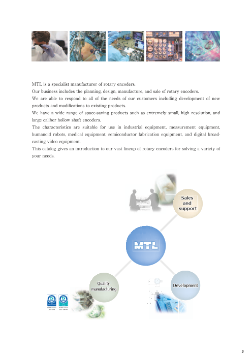
MTL is a specialist manufacturer of rotary encoders.
Our business includes the planning, design, manufacture, and sale of rotary encoders.
We are able to respond to all of the needs of our customers including development of new
products and modifications to existing products.
We have a wide range of space-saving products such as extremely small, high resolution, and
large caliber hollow shaft encoders.
The characteristics are suitable for use in industrial equipment, measurement equipment,
humanoid robots, medical equipment, semiconductor fabrication equipment, and digital broad-
casting video equipment.
This catalog gives an introduction to our vast lineup of rotary encoders for solving a variety of
your needs.
Sales
and
support
Quality Development
manufacturing
ISO 9001 certification ISO 14001 certification
JQA-1935 JQA-EM5919
2
Page4
03
MICRO ENCODER Description
MTL rotary encoders are all based on space-saving design and available in many types from ultra-small types to
high-resolution products.
Incremental
Series name Appearance Type name Outside dimensions Resolution Features Page
ME series MES-3P φ5×9.6 64P/R,100P/R ●The smallest model of ultra-small series. 7
●A, B, and Z phase output.
MES-3PST □6×8.6 1024P/R ●Open collector output. 8
MES-6- PC φ7.5×10.5 ●
100~500 A, B, and Z phase output.
9
●Open collector output.
MES-6- PST C φ7.5×10.5 10
32 ●Compactness, light weight.
●A, B, and Z phase output. 11
ME -9- P φ13×20 1,024 ●Hollow-shaft type convenient for small motors.Option
(16,000) 12●With built-in PST ×2, ×4, ×8, ×16 multiplication circuit
60 ●Compactness, light weight.
●A, B, and Z phase output. 13
ME -12- P φ20×20(S) 2,048 ●Availability of hollow-shaft type convenient for small motors.
(32,000) Option 14●With built-in PST ×2, ×4, ×8, ×16 multiplication circuit
2,250 ●Compact high-resolution incremental encoder 15MEH-14-2250 PSTN E φ21×16.5 ●(72,000) Hollow shaft with 2.6 mm inner diameter.●PSTN ×2, ×4, ×5, ×8, ×10, ×16, ×20, ×32 16
100 ●Compactness, light weight. 17
ME -17- P φ20×15 ●A, B, and Z phase output.●Availability of 3 types of shaft shape, single-shaft typesφ2
500 and φ4 and hollow-shaft type. 18
3,375 ●Compact high-resolution incremental encoder 19MEH-19-3375 PSTN E φ30×16.5 ●(108,000) Hollow shaft with 5 mm inner diameter.●PSTN ×2, ×4, ×5, ×8, ×10, ×16, ×20, ×32 20
40 ●Thin and compact popular type.
ME -20- P ●φ32×22 Availability of shaft shape to meet various fitting systems.
21
7,200 Option
(144,000) ●With built-in PST ×2, ×4, ×5, ×8, ×10, ×16, ×20 multiplication circuit 22
6,750 ●Compact high-resolution incremental encoder 23MEH-28-6750 PSTN E φ40×16.5 ●Hollow shaft with 8 mm inner diameter.(216,000) ●PSTN ×2, ×4, ×5, ×8, ×10, ×16, ×20, ×32 24
40 ●Thin and compact popular type. 25
ME -30- P φ44×22 ●Availability of shaft shape to meet various fitting systems.10,800 Option
(216,000) 26●With built-in PST ×2, ×4, ×5, ×8, ×10, ×16, ×20 multiplication circuit
20,000 ●Thickness:18㎜ 27
MEH 30T PST E φ44×18 ●- - Diameter hollow shaft:φ10㎜ ●Output pulse:200,000P/R
200,000 ●Maximum response frequency:1MHz 28
100 ●Robust, general-purpose type.
●Hostile-environment and drip-proof specifications are also available. 29
MES-40- P φ56×36.8 15,000 ●Load-resistance.
(300,000) Option 30●With built-in PST ×2, ×4, ×5, ×8, ×10, ×16, ×20 multiplication circuit
MES-45- - 360 ●φ55×50 Strong type
31
●Environment resistance
(Old model: RK1・RKW1) 9,000 32
500 ●Thin and compact popular type. 33
ME -50- P φ65×30 ●Availability of shaft shape to meet various fitting methods.10,800 Option
(216,000) 34●With built-in PST ×2, ×4, ×5, ×8, ×10, ×16, ×20 multiplication circuit
●Thin and high resolution incremental encoder 35
MEH-59- PST E φ70×16.5 1,024 ●Hollow shaft of 25 in inside diameter.(648,000) ●PSTN ×2, ×4, ×5, ×8, ×10, ×16, ×20, ×32
●PSTG ×25, ×50, ×100 36
100 ●High resolution.
●Easy-to-fit thin type. 37
MEH-60- P φ74×30 21,600 ●Large hollow shaft of 30 in inside diameter.
(432,000) Option 38●With built-in PST ×2, ×4, ×5, ×8, ×10, ×16, ×20 multiplication circuit
150 ●High resolution.
●Easy-to-fit thin type. 39
MEH-85- P φ100×26 21,600 ●Large hollow shaft of 36 in inside diameter.
(432,000) Option 40●With built-in PST ×2, ×4, ×5, ×8, ×10, ×16, ×20 multiplication circuit
360 ●High resolution. 41
MEH-130- P φ150×50 ●Large hollow shafts of 60 and 75 in inside diameter.36,000 Option
(720,000) 42●With built-in PST ×2, ×4, ×5, ×8, ×10, ×16, ×20 multiplication circuit
36,000 ●High resolution. 43
MEH-180- P φ200×71 ●Large hollow shaft of 90 in inside diameter.72,000 Option
(1440,000) 44●With built-in PST ×2, ×4, ×5, ×8, ×10, ×16, ×20 multiplication circuit
MGH series MGH-20- φ32×22.5 40~1,200 ●Light weight, compactness. 45
●Modular type best suited for small motors.
MGH-30- φ44×21 40~2,000 46
MG series MG-20- Diameter rotating slitφ22 100~1,200 ●Kit where the rotating slit and sensor unit are separate pieces. 47
●Compact and lightweight. Best suited for space-saving designs.
MG-30- Diameter rotating slitφ31.6 100~2,000 ●A, B, and Z phase output. 48
3
‒ ‒ ‒ ‒ ‒ ‒ ‒ ‒ ‒ ‒ ‒ ‒ ‒ ‒ ‒ ‒ ‒ ‒ ‒ ‒ ‒
~ ~ ~ ~ ~ ~ ~ ~ ~ ~ ~ ~ ~
Page5
04
MICRO
ENCODER
How to read type name
ME - - MA - - MLS- - -
Series name Series name Linear series
Shaft shape *1 Shaft shape *1 Shape
Slit diameter Slit diameter Resolution, minimum reading
Measuring length(mm)
Output pulse number・・・pulse number per rotation Resolution
Voltage output: no mark/open collector output: C/line driver output: E Output code *2
Supply voltage *3
*1 *2 *3
Single-shaft type Hole type Both-shaft type Gray Pure binary BCD DC5V DC12V DC5~12V 24V DC12~24V
S H D G N B 1 2 3 4 5
Refer to the shaft typ(e p.86)and hole typ(e p.83)for installation of the encoder.
Absolute
Series name Appearance Type name Outside dimensions Resolution Features Page
Single turn 4096 ●12bit, super-compact, smallest model in its series
type MAS-3-4096N1 φ6×8.6 2048 ●SSI interface 50
1024
256(8bit) ●Outer diameter:φ13㎜ ●Height:15.5㎜
MMS-10- G1 φ13×17.2 ●Resolution: 1024 divisions 51
1,024(10bit) ●SSI interface
●
MAS Ultra compact 8-bit absolute type-10-256G φ13×15.5 256(8bit) ●Gray code output without reading error 52
32,768(15bit)
MAS-14- N1 ●φ21×16.5 65,536(16bit) 18bit small high-resolution absolute encoder 53131,072(17bit) ●SSI interface
262,144(18bit)
256(8bit) ●Small absolute type.●Availability of single-shaf(t 4 in diameter)and hollow shaft
MA -17- 1 φ20×21 (2 in inside diameter). 54
1,024(10bit) ●The output codes are gray code, pure binary code, and
BCD code.
32,768(15bit)
MAS-18- N1 φ25×15 65,536(16bit) ●17bit small high-resolution absolute encoder131,072(17bit) 55●SSI interface
262,144(18bit)
65,536(16bit)
●
MAH-19- N1 φ30×16.5 131,072(17bit)
19bit small high-resolution absolute encoder
●Hollow shaft typ(e 5 in inside diameter)
262,144(18bit) 56●SSI interface
524,288(19bit)
256(8bit) ●Thin and compact 12-bit absolute encoder
MA -20- - 1 φ32×24 ●Availability of shaft shape to meet various fitting systems.●The output codes are gray code, pure binary code, and 57
4,096(12bit) BCD code.
262,144(18bit) ●20bit small high-resolution absolute encoder
MAH-28- N1 φ40×16.5 524,288(19bit) ●Hollow shaft typ(e 8 in inside diameter) 58
1,048,576(20bit) ●SSI interface
1048576 ●Compact 20-bit absolute encoder
MA△-36-※※※N1 φ46×30 524288 ●SSI interface 59
262144 ●Availability of shaft shape to meet various fitting systems.
256(8bit) ●Compact absolute encoder.
MA -36- φ46×30 ●Robust, hostile-environment type. 60
16,384(14bit) ●Availability of shaft shape to meet various fitting systems.
256(8bit) ●12bit absolute encoder
MA -42- φ52×30 ●The output codes are gray code, pure binary code, and 61
4,096(12bit) BCD code.
2097152 ●21bit thin high-resolution absolute encoder.
MAH-59-2097152N1 φ70×18 1048576 ●Hollow shaft of 25 in inside diameter. 62
524288 ●SSI interface
2097152 ●21bit high-resolution absolute encoder.
MAH-85-2097152N1 φ100×32 1048576 ●Large hollow shaft of 36 in inside diameter.524288 63●SSI interface
262144
Muiti turn ●Electronic multi-revolution absolute encoder.
MAS-36-1000MT ●-S φ46×30 1000×256 Single-revolution: 1,000 divisions, multi-revolution: type 64-128 to 127 rotations.
●
(Multiple-rotation) Binary output at decoder.
●Mechanical multi-revolution absolute encoder, no battery
MXH-36-256-1024GC5N φ46×37 1024×256 backup required. 65
●φ8mm fully hollow shaft.
MXS-36- - C6 φ46×55 128~1,024(10bit) ●Multiple-rotation absolute encoder 66
MXS-42-□-□□□□□□-□ φ65×63.5 128~4,096(12bit) ●Multiple-rotation absolute encoder 67
4
~ ~ ~ ~ ~
Page6
05
Wire-type linear scale
Series name Appearance Type name Features Page
Incremental ●Smallest in the series: Outside dimensions 23 x 24 x 2(5 H)
formula MLS -12- - ●Stroke: 250 mm ●Resolution: Selection from among 0.1mm, 0.04mm 69●Lightweight: 60 g
●Wire draw-out-type linear encoder. Detection of linear position to correspond to the draw-out
MLS-30- - amount of the wire.●Minimum reading 0.02mm, 0.2mm *0.005mm, 0.05mm is possible with 4-multiplying circuits. 70
●Measuring range: 500mm, 1000mm. ●Also available is a set type with indicator.
●Wire draw-out-type linear encoder. Detection of linear position to correspond to the draw-out amount
of the wire.
MLS-37-1024※◎-1500 ●Minimum reading 0.01mm *0.025mm is possible with 4-multiplying circuits. 71
●Measuring range: 1500mm.
●Compact and slim version of the MLS-50
MLS-45-540※-4000 ●Minimum reading 0.4mm *0.1mm is possible with 4-multiplying circuits. 72
●Measuring range: 4000mm.
●Wire draw-out type linear encoder. Detection of linear position corresponding to the draw-out
MLS-50- - amount of the wire.●Minimum reading 0.4mm *0.1mm is possible with 4-multiplying circuits. 73
●Measuring range: 2000mm, 4000mm. ●Also available is a set type with indicator.
Absolute ●Wire draw-out-type linear absolute encoder.
formula MLA-17- 1-60
●Smallest in the series: Outside dimensions 23 x 24 x 27.(4 H) 74
●Output 1,02(4 G, N) or 1,00(0 B)
●Main Applications: Robot Machine, small actuator, manipulator and etc.
●Wire draw-out-type linear absolute encoder.
MLA-30- -90 ●Minimum reading 0,088mm, 0,09mm 75
●Output 1,02(4 G, N) or 1,00(0 B)
●Wire draw-out-type linear absolute encoder.
MLA-37-1024GC5NV-1500 ●Reading 0.1mm 76
●Measuring range: 1500mm.
MLA-42- - ●Wire pulling linear absolute encoder Detection of absolute position does not need backup.●Resolution/measuring range: 0.1/400 mm, 0.25/1000 mm, 0.5/2000 mm, 1/4000 mm 77
Roller encoder/Counter
Roller encoder ●Roller type linear encoder.
REH series REH-30- R ●Easy measuring. 79
●Minimum reading 0.1 to 1mm.
Measuring angle/
measuring length DC- ●Small and robust counter.●Decimal point moving, dividing/multiplying possible. 80
DC series
Page
Technical data Incremental encoder 81
Timing Chart for Serial Communications 82
Fitting Method Hole Type Encoder 83
Shaft Type Encoder 86
Setting Option/Coupling List of dimensions and 84
Spring flange accessories
Special spring flange 85
Frequently Asked Questions Issuance of Certificate of Non-applicability
Shipping charges
87
Purchase method (Contact)
Troubleshooting
Limitations on use, Using our products safely
warranty 88Warranty
■For the details of products, see the page of each product.
■You are requested to consult sales personnel of our company because the
specifications, etc. may be changed for improvement without prior notice.
5
Page7
06
MICRO
ENCODER
Incremental
Abundant lineup, covering outer diameter Φ6 - Φ200mm, resolution 40P/R - 1,440,000P/R,
and hollow diameter Φ5 - Φ90mm.
Choose from single-shaft type, double-shaft type, tubular-shaft type, and hollow-shaft type.
These attributes can be combined to suit diverse applications.
MES-3P/MES-3PST MES-6P/MES-6-125PST16C ME-9-P ME-12-P MEH14
ME-17-P MEH-19 ME-20-P MEH-28 ME-30-P
MEH-30T MES-40-P MES-45 ME-50-P MEH-59
MEH-60-P MEH-85-P MEH-130-P MEH-180-P MGH
MG-20/30
6
Page8
07
MES-3P series MES-3PST series
[Square Wave/Incremental] [Square Wave/Incremental]
Actual size Actual size
■ Specifications ■ Specifications
Type name MES-3-64P Type name MES-3-64PST16
Item Item
Supply voltage DC3.2±0.1V Supply voltage DC3.2±0.1V
Current consumption 15mA or less Current consumption 20mA or less
Detection system Incremental Detection system Incremental
Output pulse number Output pulse number
(Standard) 64P/R, 100P/R (Standard)
1,024 pulse/rotation
(64 pulses/rotation multiplied ×16 electrically)
〔Pulse number/rotation〕 〔Pulse number/rotation〕
Output phase A, B, Z phase Output phase A, B, Z phase
Output form Square wave, Voltage(C-MOS)output Output form Square wave, Voltage(C-MOS)output
CMOS output: Output current IOL=+8mA, IOH=-2mA CMOS output: Output current IOL=+8mA, IOH=-2mA
Output voltage: VOL≦0.3V(when IOL=+1mA) Output voltage: VOL≦0.3V(when IOL=+1mA)
Output capacity VOH≧Vcc-0.3V(when IOH =-1mA) Output capacity VOH≧Vcc -0.3V(when IOH =-1mA)
Output withstand voltage:3.3V or less Output withstand voltage:3.3V or less
(power supply voltage or less) (power supply voltage or less)
Maximum response frequency Maximum response frequency
(response pulse number) 100kHz (response pulse number)
100kHz
A, B phase difference: T/4±T/8 Phase difference between neighboring A/B phases: T/4 ± T/8
Output phase difference Z phase T±0.5T Output phase difference Waveform ratio of 1T: T ± 0.35T
Z phase width: 1T(Synchronized with 1T of B phase)
Waveform rise/fall time 2μs or less(When 150mm flexible cable extended using 300mm AWG30 cable) Waveform rise/fall time 2μs or less(When 150mm flexible cable extended using 300mm AWG30 cable)
Allowable load of Radial 0.98N(100gf) Allowable load of Radial 0.98N(100gf)
shaf(t electrical) Thrust 0.98N(100gf) shaf(t electrical) Thrust 0.98N(100gf)
Maximum allowable revolutions
(mechanical) 6,000r/min Maximum allowable revolutions(mechanical) 6,000r/min
Working ambient temperature/ 0℃~60℃
humidity Working ambient temperature/
0℃~60℃
RH35%~90% no dewing humidity RH35%~90% no dewing
Storing ambient temperature -20°C~80°C Storing ambient temperature -20°C~80°C
Vibration resistance Durability 55Hz, double amplitude 1.5mm Vibration resistance Durability 55Hz, double amplitude 1.5mm2 hours each in X, Y, and Z directions 2 hours each in X, Y, and Z directions
2 2
Impact resistance Durability 500m/s(about 50G) Impact resistance Durability 500m/s (about 50G)
3 times each in X, Y, and Z directions 3 times each in X, Y, and Z directions
Cable Flexible cable: Length approx. 150mm Cable Flexible cable: Length approx. 150mm
Mass 5g(including flexible cable) Mass 5g(including flexible cable)
■ Output circuit diagram(ME-3P、ME-3PST) ■ Output waveform(ME-3P) ■ Output waveform(ME-3PST)
CW rotation(CW rotation as seen from fit surface) CW rotation(CW rotation as seen from fit surface)
Ts
T
T T1 T2 T15 T16
t
T/4±T/8 t1 t2 t3 t4 t5 t6 t7 t8 t~ t57 t58t59 t60 t61 t62t63 t64
+Vcc(DC3.2V±0.1V) H A phase
A phase
L
IOH=-2mA
H B phase
Outpu(t A/B/Z) B phase
IOL=+8mA L
H Z phase
0V Z phase A, B phase Waveform ratio of 1T T=Ts/16±0.35T
L Phase difference of A, B phase adjacent to 16 divisions T/4=±1/8T
T±T/2 Waveform ratio of 1/4T t1~t64=t±0.35t
Z phase Z=1.0T Synchronized with B phase
*The position of Z phase against
A, B phase is not specified. Tmax Tmin Tmin/Tmax≧0.5
Waveform
example
7
Output
Main circuit
Output
Page9
08
MICRO
ENCODER
■ Outside dimensions ■ Outside dimensions
MES-3P MES-3PST
150±2 150±2
Exposed copper foil surface
3+0.1 Connector for matching FPC connection-0.1
R0.3 Japan Aviation Electronics Industry IL-FPR-8S-HF-N1
Exposed
conductor
surface
Connector for matching FPC connection
Japan Aviation Electronics Industry IL-FPR-6S-HF-N1
M4 thread(fine thread)
Exposed copper foil surface
Reinforcing
plate
Black silicon seal
Lock nu(t included)details Lock nu(t included)details
5.8+0.1 +0.10 5.8 0
A M4 × P0.5 20°20° A M4 × P0.5 20°20°
(fine thread) (fine thread)
Reinforcing plate Exposed
conductor surface
A A
A 1.5 A 1.5
A-A cross-section A-A cross-section
Terminal board(included)details Terminal board(included)details
10(Pich 2×5) Wiring chart 14(Pich 2×7) Wiring chart
Pich 2
φ TH No. Signal name
Pich 2 8-φ0.6TH TH No. Signal name
6- 0.6TH 1 2 3 4 5 6 7 8
1 2 3 4 5 6 1 Vcc(DC3.2V±0.1V) 1 Vcc(DC3.2V±0.1V)
2 N.C(. Not connected)
2 Z phase output 3 N.C(. Not connected)
3 0V 4 Vcc(DC3.2V±0.1V)
4 A phase output 5 Z phase output
6 B phase output
5 B phase output
15 FPC insertion direction 18 FPC insertion direction
7 A phase output
6 0V 8 0V
Connector: Japan Aviation Electronics Industry Connector: Japan Aviation Electronics Industry
IL-FPR-6S-HF-N1 IL-FPR-8S-HF-N1
8
9.6+0.1-0.1 3.7+0.-0.(11 H cut)
7.1+0.1 2.5+0.1 3+0.1-0.1 -0.1 -0.1
5 (2.2)(5) φ
13 5 +
15 - 00 .. 11
( (6.7)φ5.8)
2.6
φ5.8
φ5.8
6.1 2.5+0.1 +0.1 6
+0.1
±0.1 -0.1 3-0.1 -0.1
3.7+0.(1R -0.1 H cut)3
5 (2.2)
(5) 2
13 2.6
15
(6.7)
( 3.8φ5.8)
φ5.8
4.5
φ5.8
0.3C
0.3C
005.
5-
0 .01
5
1. -
0
φ
0.3C
.3
C0
05.0 15
-00.0
1.5
-
φ
Page10
09
MES-6-P series MES-6-125PST16C
[Square Wave/Incremental] [Square Wave/Incremental]
Actual size Actual size
■ Specifications ■ Specifications
Type name MES-6- PC Type name MES-6- PST C
Item Pulse number Item Pulse number Multiplication
Supply voltage DC5V ±10% Supply voltage DC5V ±5%
Current consumption 30mA or les(s under no load) Current consumption 30mA or less
Detection system Incremental Detection system Incremental
Output pulse number 100 300 Output pulse number 2,000P/R(125×16), 2048P/R(128×16)
(Standard) 120 360 (Standard) 1,000P/R(125×8), 1,024P/R(128×8)
〔Pulse number/rotation〕 200 500 〔Pulse number/rotation〕 500P/R(125×4), 512P/R(128×4)
Output phase A, B, Z phase
Output phase A, B, Z phase
Output form Square wave, open collector output Output form Square wave, open collector output
Output capacity Sink current :4mA(output voltage resistance 7V)
Residual voltage:0.4V or less Output curren:t 4mA maxOutput capacity output voltage resistance: 5.25V or less
Maximum response frequency
(response pulse number) 100kHz (power supply voltage or less)
Maximum response frequency
Output phase difference A, B phase difference 90°±45(°T/4±T/8) (response pulse number)
100kHz
Z phase T±T/2(see Output Waveform)
Allowable load of Radial 1.9N(200gf)
Waveform rise/fall time 2μs or les(s output cable 300mm or less) shaf(t electrical) Thrust 0.98N(100gf)
Allowable load of Radial 1.9N(200gf) Maximum allowable revolutions
(mechanical) 6,000r/minshaf(t electrical) Thrust 0.98N(100gf) Working ambient temperature/ 0℃~60℃
Maximum allowable revolutions
(mechanical) 6,000r/min humidity RH35%~90% no dewing
Working ambient temperature/ 0℃~60℃ Storing ambient temperature -20°C~80°C
humidity RH35%~90% no dewing
Vibration resistance Durability 55Hz, double amplitude 1.5mm
Storing ambient temperature -20℃~80℃ 2 hours each in X, Y, and Z directions
Vibration resistance Durability 55Hz, double amplitude 1.5mm
2
Impact resistance Durability 500m/s(about 50G)
2 hours each in X, Y, and Z directions 3 times each in X, Y, and Z directions
Impact resistance Durability 500m/s(
2 about 50G) Cable Vinyl wire(AWG32)
3 times each in X, Y, and Z directions Cable length 300mm
Cable Vinyl wire(AWG32)
Mass 5g
Cable length 300mm
Mass 5g
■ Output circuit diagram(ME-6P) ■ Output circuit diagram(ME-6PST)
Open collector output
Cable color
Vcc(5V±5%)
Powe(r red)
A, B, Z Outpu(t A, B, Z phase)
(white, green, yellow)
4mA maximum
0V(black) IOL=4mA max0V
Supply voltage
DC5V
9
Output
Main circuit
Main circuit
Output
Page11
10
MICRO
ENCODER
■ Outside dimensions
MES-6P. PST
5 0-0.1
φ1.5-0.005-0.015
Output cable 5-AWG32
L=300±10mm
Name plate Repeated bending not allowable
Accessor(y lock nut)
t=1.5
M6×0.5
■ Output waveform(ME-6P) ■ Output waveform(ME-6PST)
CW rotation CCW rotation CW rotation(CW rotation as seen from fit surface)
(CW rotation as seen from fit surface) (CCW rotation as seen from fit surface) T
t
T T
H H
A phase L A phase L
A phase
H H
B phase L B phase L
̶T±T(̶90°±45°) ̶T±T(90°±45°)
4 8 4 8̶ B phase
H H
Z phase L Z phase L
T±T/2 T±T/2 Z phase
T±T/2
*The position of Z phase against A, B phase is not specified.
T: Waveform ratio of 1T T = T±0.35T
t : Phase difference between adjacent A and B phases t = 1/4 T±0.3t
10
φ7.5±0.1
10.5 0±0.1 3±0.1 φ6-0.1
8±0.1 2.5
±0.1
8
2±0.1
M6 P0.5
5-φ0.58
Page12
11
ME-9-P series
[Square Wave/Incremental]
■ Specifications
Type name ME -9- P
Shaft shape Pulse Output circuit
●S=single shaft number ●Noentry=Voltage putput ●ST□(2・4・8・16)
●H=hollow shaft ●C=open collector output
Item ●E=line driver output
Square wave Built-in multiplication circui(t ×2・×4・×8・×16)
Supply voltage DC5V ±10% DC5V ±5%
Current consumption 40mA or les(s under no load) 50mA or les(s under no load)
Detection system Incremental Incremental
Output pulse number 32 300 900(*) EX 1,000×2(2,000)
(Standard) 100 360 1,000(*) 1,000×4(4,000)200 500 1,000×8(8,000)
〔Pulse number/rotation〕 1,024256 1,000×16(16,000)
Output phase A, B, Z phase( Z=“H”) A, B, Z phase
Output form Square wave Square wave
Sink current:20mA Sink current:20mA max.
Output capacity Residual voltage:0.5V or les(s at 10mA) Residual voltage:0.5V or les(s at 10mA)
Open collector output:Load voltage DC13.2V max Open collector output:Load voltage DC13.2V max
Maximum response frequency Open collector outpu:t 100kHz
(response pulse number) 100kHz Line driver output:50kHz×(by multiplication)
Output phase difference A, B phase difference 90°±45(°T/4±T/8) Refer to the figure on the rightZ phase T±T/2(see Output Waveform)
Waveform rise/fall time 2μs or les(s output cable 140mm or less) 1μs or les(s output cable 140mm or less)
Allowable load of Radial 1.9N(200gf) 0.98N(100gf) 0.98N(100gf)
shaf(t electrical) Thrust 1.9N(200gf) 0.98N(100gf) 0.98N(100gf)
Maximum allowable revolutions
(mechanical) 6,000r/min 6,000r/min
Working ambient temperature/ 0℃~60℃ 0℃~60℃
humidity RH35%~90% no dewing RH35%~90% no dewing
Storing ambient temperature -20°C~80°C -20°C~80°C
Vibration resistance Durability 55Hz, double amplitude 1.5mm Durability 55Hz, double amplitude 1.5mm2 hours each in X, Y, and Z directions 2 hours each in X, Y, and Z directions
2 2
Impact resistance Durability 500m/s(about 50G) Durability 500m/s(about 50G)
3 times each in X, Y, and Z directions 3 times each in X, Y, and Z directions
Voltage・Open collecto:r Vinyl wire(AWG30) Open collecto:r Vinyl wire(AWG30)
Cable Cable length 140mm Cable length 140mmLine drive・r Vinyl wire(AWG32) Line drive・r Vinyl wire(AWG32)
Cable length 330 Cable length 330
Mass 10g 20g
*Handled by built-in multiplier circuit Note: Types with a built-in internal multiplier circuit do not support voltage output
11
Output
Page13
12
MICRO
ENCODER
■ Outside dimensions ■ Output circuit diagram(Square wave)
Voltage outpu(t standard type) Open collector outpu(t option) Line driver outpu(t option)
AWG30
MES-9-P Cable colorL=140 Cable color Cable color
+5VDC(red)
Powe(r red) Powe(r red) A, B, Z (white, green, yellow)
2.2kΩ A, B, Z A, B, Z -A, -B, -Z( brown,
(white, green, yellow) (white, green, yellow) blue, orange)
26C31
20mA maximum 20mA maximum 0V(black)
0V(black) 0V(black) (shield)
Main body—shield no connection
φ13(max.φ13.5) Supply voltage DC5V
Supply voltage Supply voltage Note: If the transmission distance is
DC5V DC5V long, it should be so considered that the specified voltage occurs at the input
portion of the encoder cable end.
φ1.5-0.005-0.015 ■ Output waveform(Square wave)Voltage/Open collector ■ Output waveform(Square wave)Line driver
CW rotation (CW rotation as seen from fit surface) CW rotation (CW rotation as seen from fit surface)
T T
H
A pahe T/4±T/8L H
A phase L
- H
H A phase L
B pahe L HB phase L
2-M2 depth 3 equal ̶T±T(̶90°±45°) - H4 8 B phase L
arrangement H
PCD=10 H
Z phase L
Z pahe L - HZ phase L T±T/2
T±T/2
φ13(maxφ13.5) *The position of Z phase against A, B phase is not specified. *The position of Z phase against A, B phase is not specified.
MEH-9-P AWG30
L=140 ■ Output connection diagram/Built-in multiplication circui(t ×2・×4・×8・×16)
Red +5VDC
White(green, yellow)
Output
Encoder Black 0V
Cable color Red Black White Green Yellow Brown Blue Orange
Signal +5V 0V A phase B phase Z phase -A phase -B phase -Z phase
*Line driver output.
φ1.5+0+0.01 ■ Output waveform Open collector output/Built-in multiplication circui(t ×2・×4・×8・×16)
φ8 CW rotation(CW rotation as seen from fit surface)
2-M2 90° arrangement T
t
A phase
2-M2 depth 2
12 B phase
Z phase
1T
■ Spring flange MEH-9(Included) Synchronous with 1T of B phase
T: Waveform ratio of 1T T=T±0.35(-T16)
T±0.4(-T8)
T±0.2(-T4,-T2)
t: Phase difference between adjacent A and B phases
t=T/4±1/8T
4-R1 ■ Output waveform Line driver output/Built-in multiplication circui(t ×2・×4・×8・×16)
φ CW rotation(CW rotation as seen from fit surface)6.2 Ts
T
T1 T2 T(#-1) T(#)
14 tφ t1 t2 t3 t4 t5 t6 t7 t8 t~ (t 4#-4) (t 4#)
H
4-φ2.2 PCD10 A phase L
A phase HL
B phase HL
B phase HL
2-φ2.2 4-R0.5 Z phase HL
4.5 Z phase HL 1T
Synchronous with 1T of B phase
T: Waveform ratio of 1T T=T±0.35(-T16)
T±0.4(-T8)
T±0.2(-T4,-T2)
t: Phase difference between adjacent A and B phases
t=T/4±1/8T
Waveform Tmax Tmin Tmin/Tmax≧0.5
example
12
10 10 20(PS, PST:21.5)
2
2.5
26.8
4 5.515.5(S,ST:17)
32.4
21(S,ST:22.5)
Main circuit
Main circuit
Main circuit
45゚
Page14
13
ME-12-P series
[Square Wave/Incremental]
■ Specifications
Type name ME -12- P
Shaft shape Pulse Output circuit
●S=single shaft number ●Noentry=Voltage putput ●ST□(2・4・8・16)
●H=hollow shaft ●C=open collector output
Item ●E=line driver output
Square wave Built-in multiplication circu(it ×2・×4・×8・×16)
Supply voltage DC5V ±10% DC5V ±5%
Current consumption 40mA or les(s under no load) 60mA or les(s under no load)
Detection system Incremental Incremental
Output pulse number 60 300 1,000(*) 1,500(*) EX 2,000×2(4,000)
100 360 1,024(*) 1,800(*)
(Standard) 125(*) 500 2,000(*) 2,000×4(8,000)
200 600 2,048(*) 2,000×8(16,000)
〔Pulse number/rotation〕 256(*) 900 2,000×16(32,000)
Output phase A, B, Z phase A, B, Z phase
Output form Square wave Square wave
Sink current:20mA Sink current:20mA max.
Output capacity Residual voltage:0.5V or les(s at 10mA) Residual voltage:0.5V or less (at 10mA)
Open collector output:Load voltage DC13.2V max Open collector output:Load voltage DC13.2V max
Maximum response frequency Line driver output:50kHz×(by multiplication)
(response pulse number) 100kHz Voltage outpu・t Open collector outpu:t 100kHz
Output phase difference A, B phase difference 90°±45(°T/4±T/8) Refer to the figure on the right
Z phase T±T/2(see Output Waveform)
Waveform rise/fall time 2μs or les(s output cable 1m or less) 2μs or les(s output cable 1m or less)
Allowable load of Radial 1.9N(200gf) 0.98N(100gf) 0.98N(100gf)
shaft (electrical) Thrust 1.9N(200gf) 0.98N(100gf) 0.98N(100gf)
Maximum allowable revolutions
(mechanical) 6,000r/min 6,000r/min
Working ambient temperature/ -10℃~70℃ -10℃~70℃
humidity RH35%~90% no dewing RH35%~90% no dewing
Storing ambient temperature -20°C~80°C -20°C~80°C
Vibration resistance Durability 55Hz, double amplitude 1.5mm Durability 55Hz, double amplitude 1.5mm2 hours each in X, Y, and Z directions 2 hours each in X, Y, and Z directions
Impact resistance Durability 500m/s(
2 about 50G) Durability 500m/s(2 about 50G)
3 times each in X, Y, and Z directions 3 times each in X, Y, and Z directions
Outside diameter φ3 5-core vinyl wire AWG28 Outside diameter φ3 5-core vinyl wire AWG28
Cable Insulated shield cable(length 1m) Insulated shield cable(length 1m)
Mass 40g 40g
*Handled by built-in multiplier circuit
13
Output
Page15
14
MICRO
ENCODER
■ Outside dimensions ■ Output circuit diagram
Voltage outpu(t standard type) Open collector outpu(t option) Line driver outpu(t option)
MES-12-P φ20 Cable color
Cable color Cable color
+5VDC(red)
Powe(r red) Powe(r red) A, B, Z (white, green, yellow)
2.2kΩ A, B, Z A, B, Z -A, -B, -Z( white/black,
(white, green, yellow) (white, green, yellow) green/black, yellow/black)
26C31
20mA maximum 20mA maximum 0V(black)
0V(black) 0V(black) (shield)
(shield) (shield) Main body—shield no connection
Main body—shield no connection Main body—shield no connection
Note: If the transmission distance is
long, it should be so considered that the
φ4 specified voltage occurs at the input
Output cable 1m portion of the encoder cable end.φ2-0.005-0.015 A capacito(r 0.1μF)is connected between 0V and FG(frame ground).
Note: This capacitor is not connected to the voltage or open collector output of the built-in multiplier circuit.
2-M2 depth 3
PCD=16 ■ Output waveform(Square wave)
CW rotation(CW rotation as seen from fit surface) CCW rotation(CCW rotation as seen from fit surface)
T T
H H
A phase L A phase L
H H
B phase L B phase L
̶T±T4 8̶(90°±45°) ̶
T T
4 ± 8̶(90°±45°)
H H
Z phase L Z phase L
T±T/2 T±T/2
*The position of Z phase against A, B phase is not specified.
MEH-12-P φ20
■ Output waveform/Built-in multiplication circui(t ×2・×4・×8・×16)
CW rotation(CW rotation as seen from fit surface)
T
t
φ7 A phase
φ3+0.010
2-M2 2-M2 depth 3
90°arrangement
19 B phase
Z phase
Output cable 1m T±T/2
T = T±0.3T
t = 1/4 T±0.3t
■ Spring flange MEH-12(Included)
4-R1
45゚
φ20
φ10
4-φ2.2 PCD16
2-φ2.2
4.5 4-R0.5
14
4 25 10 20
10 1
2
2.5
5.5 55゚
φ3
φ3
33.8 8
3
39.4
Main circuit
Main circuit
Main circuit
35゚
Page16
15
MEH-14 series
[Square Wave/Incremental]
Outside dimensions φ21×16.5mm
Through Shaft
■ Specifications
Type name
MEH-14-2250 PSTN E
Item
Detection system Incremental
Output phase A, -A, B, -B, Z, -Z phase CS phase(U, -U, V, -V, W, -W)
Output form Square, Line driver output
2250, 4500(2250×2), 9000(2250×4)
Output pulse
numbe(r P/R) 11250(2250×5), 18000(2250×8), 22500(2250×10)
36000(2250×16), 45000(2250×20), 72000(2250×32)
Phase difference between neighboring A/B phases: T/4 ± T/8
Output Waveform ratio of 1T: T ± 0.3t
Z phase width: T ± T/2(Synchronized with 1T of B phase)
Supply voltage DC5V±5%
Current consumption 150mA or less
Maximum response
frequency 50kHz×division ratio(2, 4, 5, 8, 10, 16, 20, 32)
Output capacity Output curren(t Io): ±20mAmax.Output voltage Vo:l 0.5Vmax. VoH: 2.5Vmin.
Maximum allowable
revolutions 6000r/min
Working ambient temperature/
humidity -10℃~+70℃/RH35%~90% no dewing
Storing ambient
temperature -20℃~+80℃
Vibration resistance Durability 55Hz, double amplitude 1.5mm 2 hours each in X, Y, and Z directions
Impact resistance Durability 50G 3 times each in X, Y, and Z directions
Cable Outside diameter φ3.0 8-cores shield cable(without CS phase: 14-cores)AWG30
Mass 35g(excluding cable)
15
Page17
16
MICRO
ENCODER
■ Outside dimensions ■ Output circuit diagram
Line driver output
Cable color
+5VDC(red)
A, B, Z
(purple, green, yellow)
-A, -B, -Z( purple/black,
green/black, yellow/black)
26C31
0V(black)
(shield)
φ3.4 Main body—shield no connection
Note: If the transmission distance is long, it should be
so considered that the specified voltage occurs at the
input portion of the encoder cable end.
Output cable
L=1,000
■ Output waveform[×1]
CW rotation(CW rotation as seen from fit surface)
T
T/4±T/8
φ2.6H7 +0.01 H 0 A phase L
- H
φ6 A phase L
H
B phase
φ21 L- HB phase L
H
Z phase L
- HZ phase L T±T/2
*The position of Z phase against A, B phase is not specified.
2-M2 depth 3
PCD16 ■ Output waveform/Built-in multiplication circui(t ×2・×4・×5・×8・×10・×16・×20・×32)
CW rotation(CW rotation as seen from fit surface)
Ts
T
T1 T2 T(#-1) T(#)
t
t1 t2 t3 t4 t5 t6 t7 t8 t~ (t 4#-4) (t 4#)
A phase HL
A phase HL
B phase HL
B phase HL
Z phase HL
Z phase HL
A, B phase ●1T waveform rate: T=Ts/#±0.3T
●Phase difference between neighboring A and B phases in # divisions: T/4±T/8
●T/4 waveform ratio: t1 to t (4#)=t±0.3t
Z phase ●Z=1.0T (synchronized with B phase)
Waveform Tmax Tmin Tmin/Tmax≧0.5
example
■ Spring flange MEH-14(Option)
4-R1
45゚
φ20
φ10
4-φ2.2
PCD16
2-φ2.2
4.5 4-R0.5
16
0.75 16.5 0.75
55°
33.8
39.4
φ3
Main circuit
Page18
17
ME-17-P series
[Square Wave/Incremental]
■ Specifications
Type name ME -17- P
Shaft shape Pulse number
●S(2)=φ2 single shaft Output circuit
●S(4)=φ4 single shaft ●Noentry=Voltage putput
Item ●H=hollow shaft ●C=open collector output
Supply voltage DC5V ±10%
Current consumption 30mA or les(s under no load)
Detection system Incremental
Output pulse number 100 300 500
(Standard) 200 360
〔Pulse number/rotation〕 256 400
Output phase A, B, Z phase(Z=“H”)
Output form Square wave, voltage output onlyPull-up resistance 10kΩ
Output capacity Sink current:20mAResidual voltage:0.4V or les(s at 10mA)
Maximum response frequency
(response pulse number) 50kHz
Output phase difference A, B phase difference 90°±45(°T/4±T/8)Z phase T±T/2(see Output Waveform)
Waveform rise/fall time 2μs or less
Allowable load of Radial 1.9N(200gf)
shaf(t electrical) Thrust 1.9N(200gf)
Maximum allowable revolutions 6,000r/min
(mechanical)
Working ambient temperature/ 0℃~50℃
humidity RH35%~90% no dewing
Storing ambient temperature -20°C~80°C
Vibration resistance Durability 55Hz, double amplitude 1.5mm2 hours each in X, Y, and Z directions
Impact resistance Durability 500m/s(
2 about 50G)
3 times each in X, Y, and Z directions
Cable Vinyl wire AWG28 150mm
Mass 20g
17
Output
Page19
18
MICRO
ENCODER
■ Outside dimensions ■ Output circuit diagram
Voltage outpu(t standard type) Open collector outpu(t option) Line driver outpu(t option)
Cable color
MES(2)-17-P 2-M2 depth 4 Cable color Cable color +5VDC(red)
PCD=16 A, B, Z
Powe(r red) Powe(r red) (white, green, yellow)--
10kΩ A, B,
-Z( white/black,
A, B, Z A, B, Z green/black, yellow/black)
(white, green, yellow) (white, green, yellow) 26C31
0V(black)
20mA maximum 20mA maximum (shield)
0V(black) 0V(black)
(shield) (shield) Main body—shield no connection
150+20-0 Main body—shield no connection Main body—shield no connection
Note: If the transmission distance is
long, it should be so considered that the
φ20 specified voltage occurs at the input
portion of the encoder cable end.
φ4 A capacito(r 0.1μF)is connected between 0V and FG(frame ground).
φ2-0.005-0.015
■ Output waveform
CW rotation(CW rotation as seen from fit surface) CCW rotation(CCW rotation as seen from fit surface)
T T
Soldering H HA phase L A phase L
About 10 AWG28(outside diameter φ0.8) H H
Vinyl wire B phase
L B phase L
̶T±T(̶90°±45°) ̶T±T(̶90°±45°)
4 8 4 8
H H
Z phase L Z phase L
T±T/2 T±T/2
*The position of Z phase against A, B phase is not specified.
MES(4)-17-P 2-M2 depth 4
PCD=16
150+20-0
φ20
φ4-0.005-0.015
Soldering
About 10 AWG28(outside diameter φ0.8)
Vinyl wire
■ Spring flange MEH-17(Option)
MEH-17-P 2-M2 depth 4
PCD=16
4-R1
45゚
150+20 2‐M2 90° φ-0 arrangement 20
φ20 φ10
φ8
φ2+0.015-0
4-φ2.2 PCD16
Soldering
About 10 2-φ2.2AWG28(outside diameter φ0.8) 4.5 4-R0.5
Vinyl wire
18
10
2.25 1
15 5 15 10 15 10
20 25 25
33.8
39.4
Main circuit
Main circuit
Main circuit
Page20
19
MEH-19 series
[Square Wave/Incremental]
Outside dimensions φ30×16.5mm
Through Shaft
■ Specifications
Type name
MEH-19-3375 PSTN E
Item
Detection system Incremental
Output phase A, -A, B, -B, Z, -Z phase CS phase(U, U, V, -V, -W, -W)
Output form Square, Line driver output
Output pulse 3375, 6750(3375×2), 13500(3375×4)
numbe(r P/R) 16875(3375×5), 27000(3375×8), 33750(3375×10)
54000(3375×16), 67500(3375×20), 108000(3375×32)
Phase difference between neighboring A/B phases: T/4 ± T/8
Output Waveform ratio of 1T: T ± 0.3t
Z phase width: T ± T/2(Synchronized with 1T of B phase)
Supply voltage DC5V±5%
Current consumption 150mA or less
Maximum response
frequency 50kHz×division ratio( 2, 4, 5, 8, 10, 16, 20, 32)
Output capacity Output curren(t Io): ±20mAmax.
Output voltage Vo:l 0.5Vmax. VoH: 2.5Vmin.
Maximum allowable
revolutions 6000r/min
Working ambient temperature/
humidity -10℃~+70℃/RH35%~90% no dewing
Storing ambient
temperature -20℃~+80℃
Vibration resistance Durability 55Hz, double amplitude 1.5mm 2 hours each in X, Y, and Z directions
Impact resistance Durability 50G 3 times each in X, Y, and Z directions
Cable Outside diameter φ4.2 8-cores shield cable(without CS phase: 14-cores)AWG30
Mass 57g(excluding cable)
19